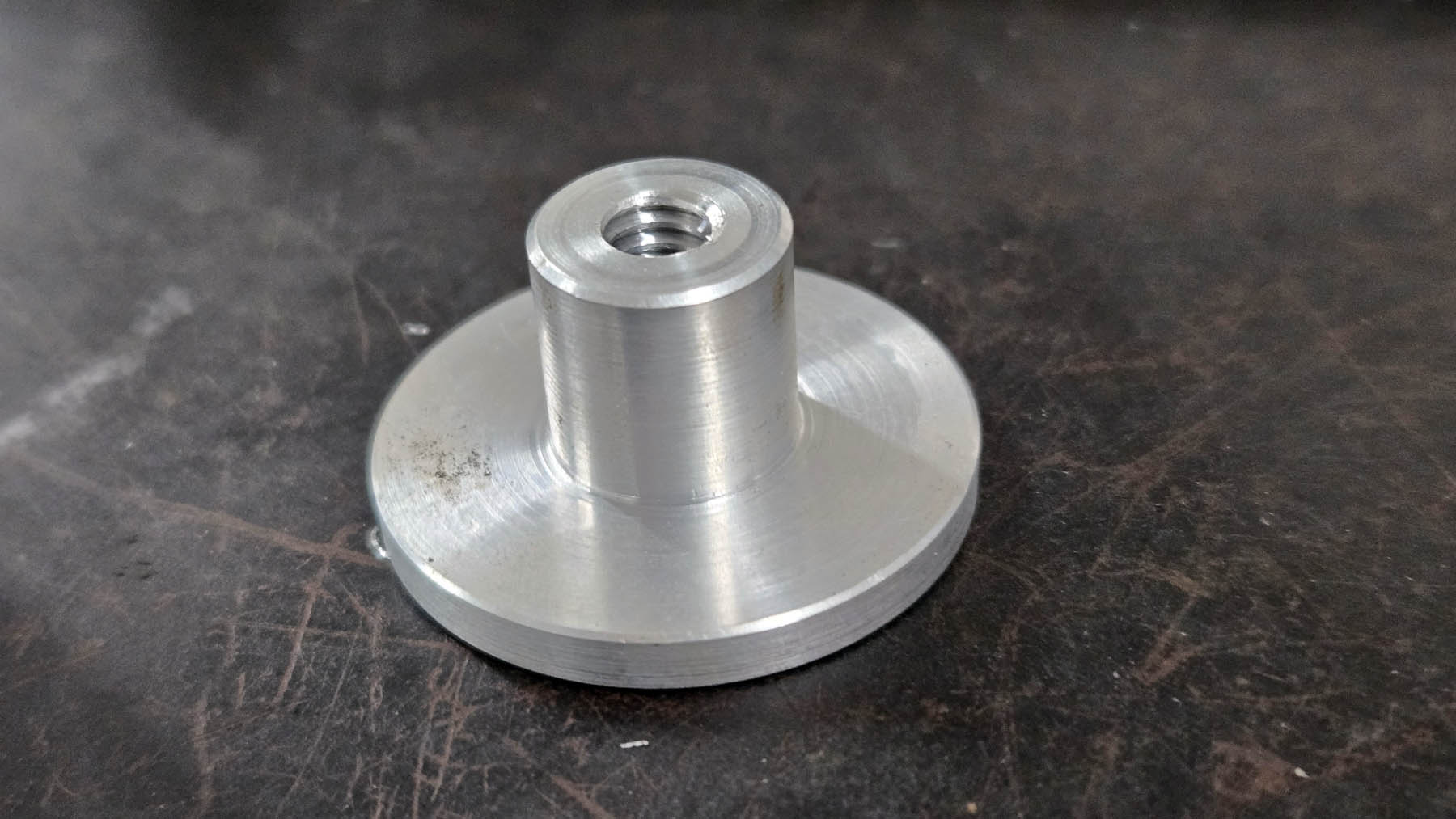
Hardware Build

Nothing here is an off-the-shelf wheelchair part.  Everything was designed and made for a specific purpose.  There were a few design characteristics limited due to the equipment I have to build with along with physical limitations.
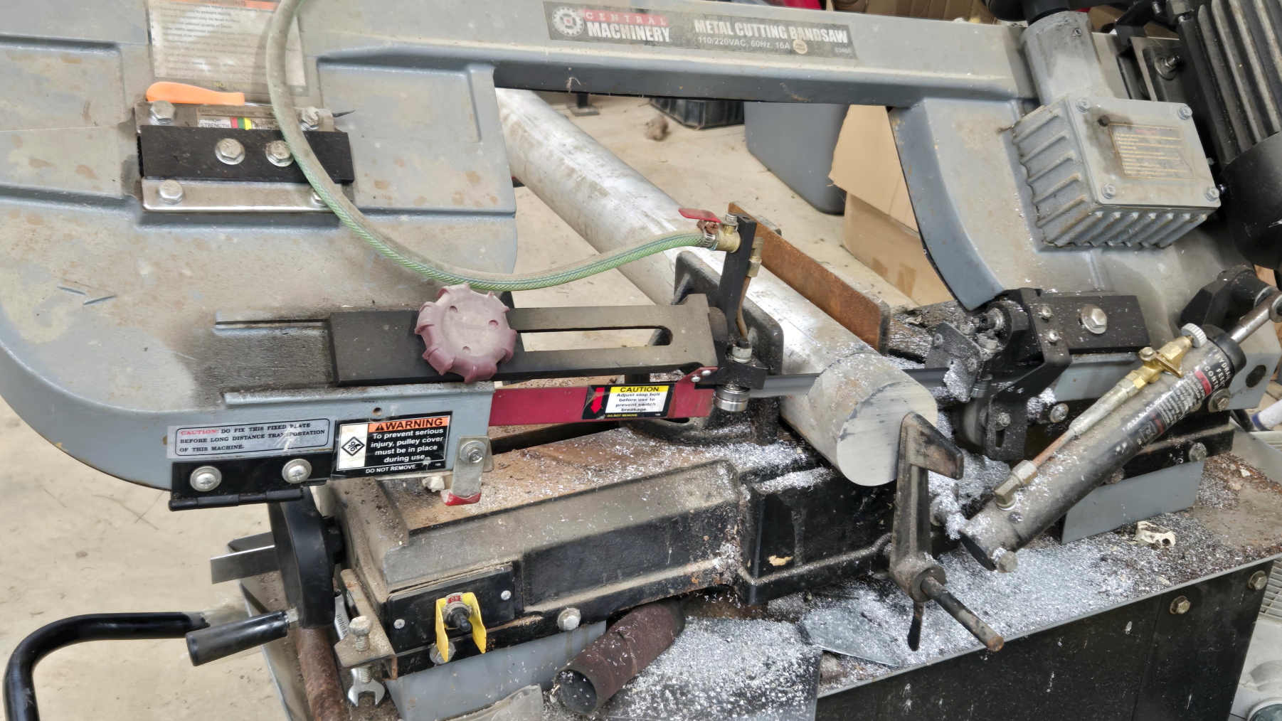
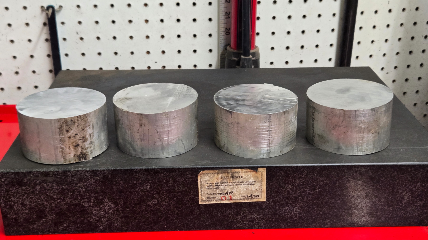
Saw Stock 1
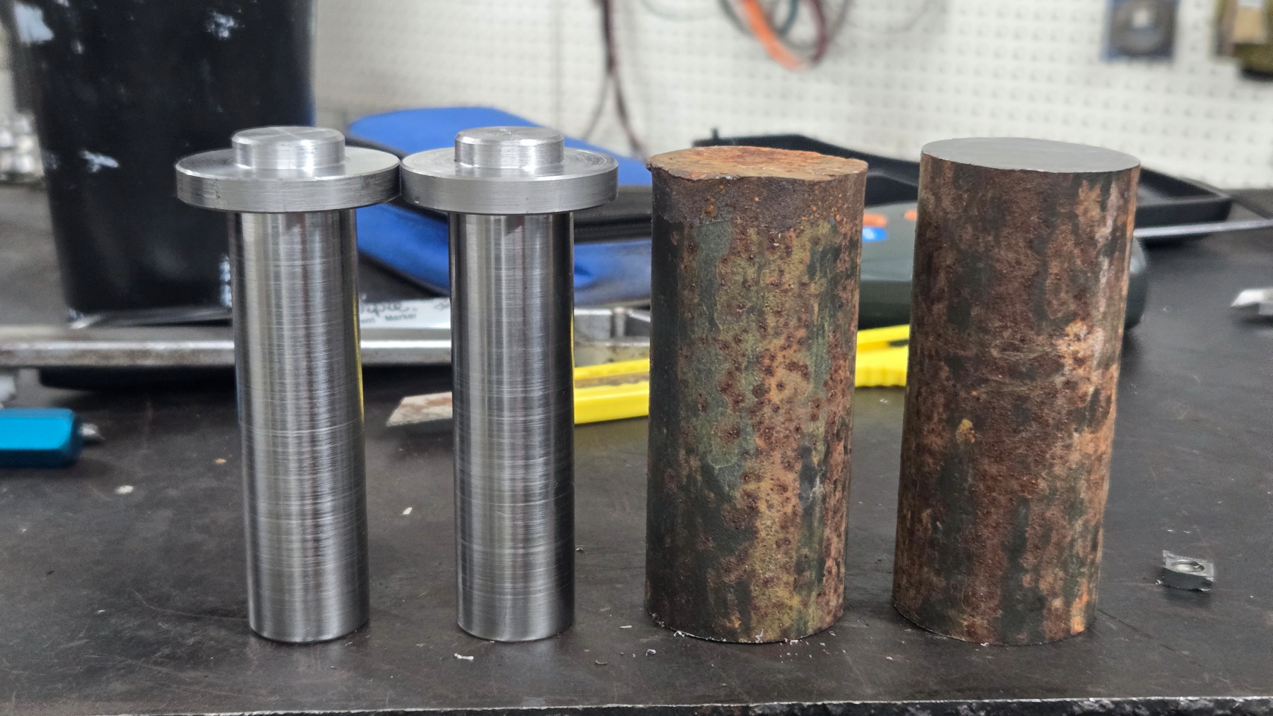
This is how most parts start out.  Long pieces of round or bar stock.  The first step is cut to length in the saw.
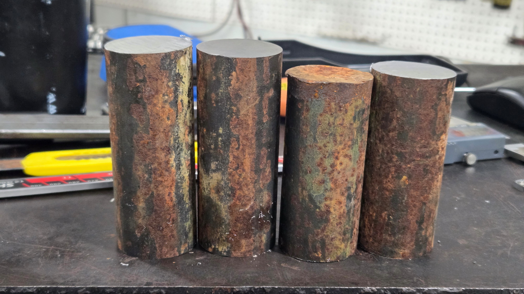
Swingarm Mount 2
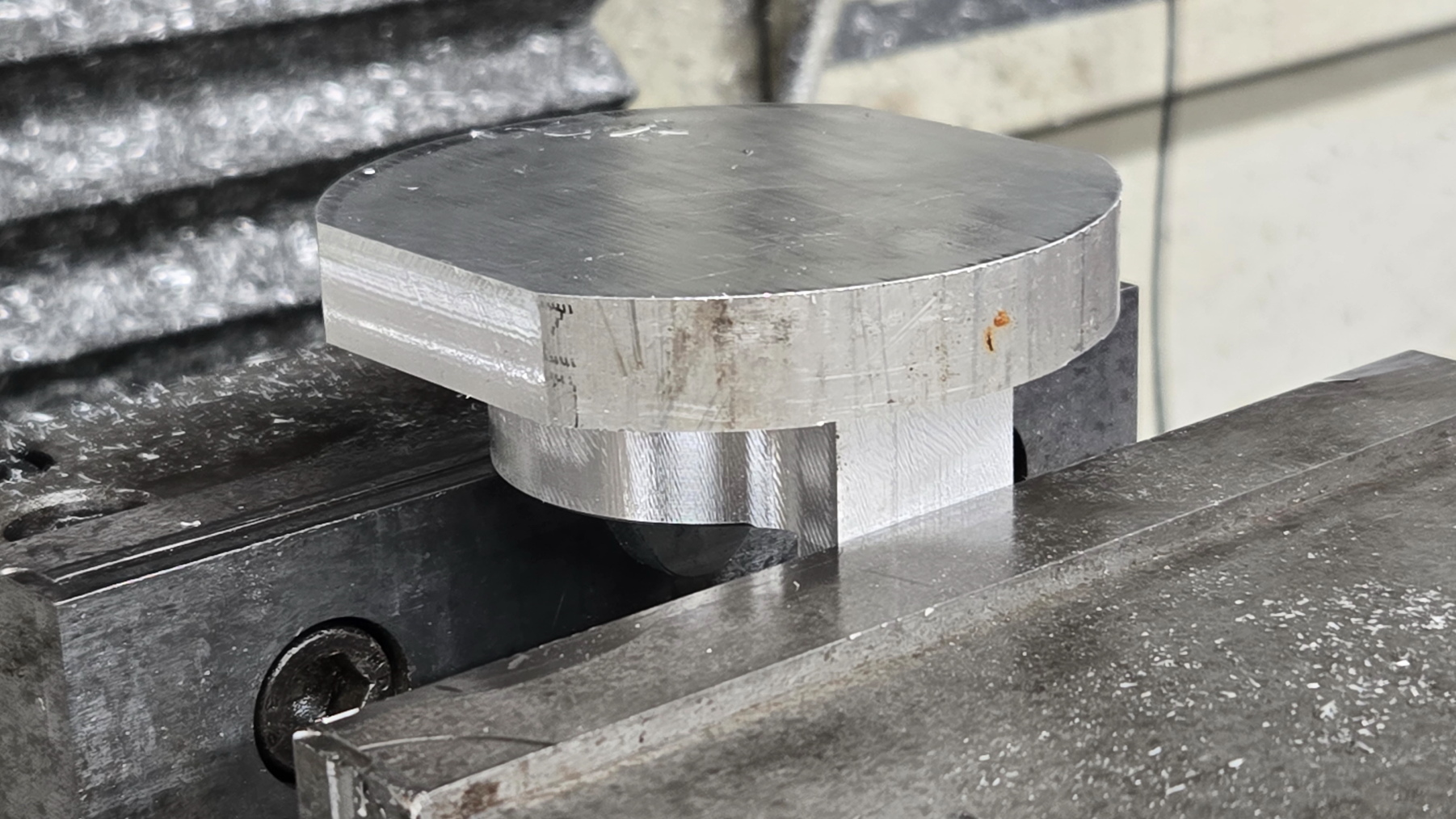
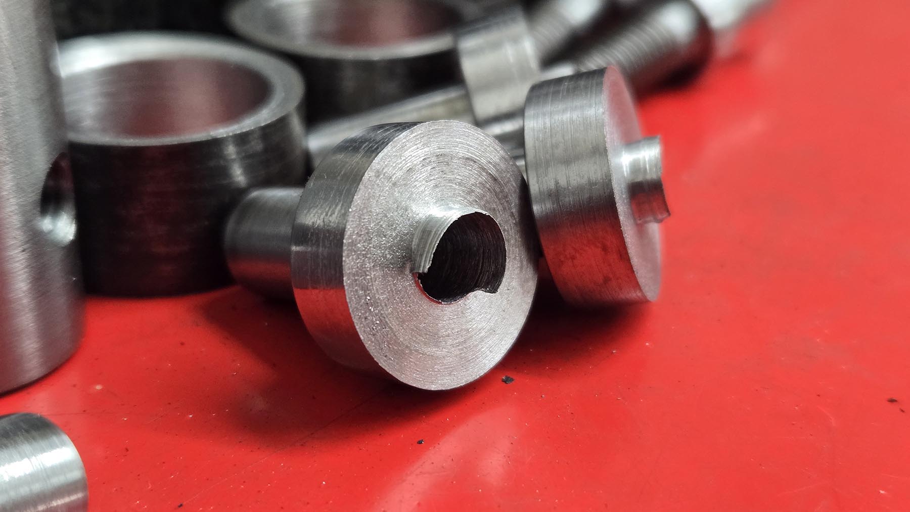
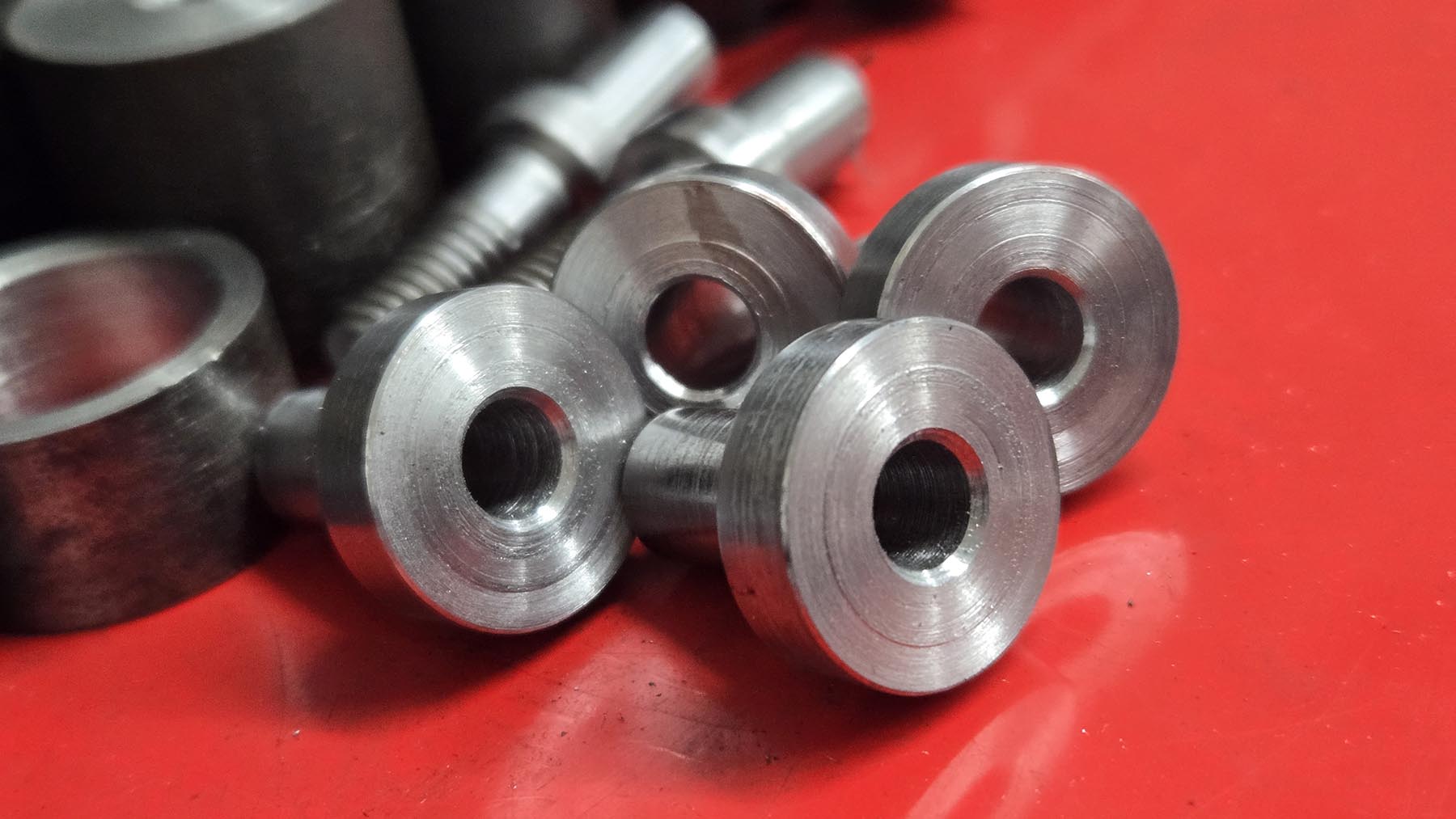
These will become the swingarm mounts.  This is for two sets.
Swingarm Mount 14
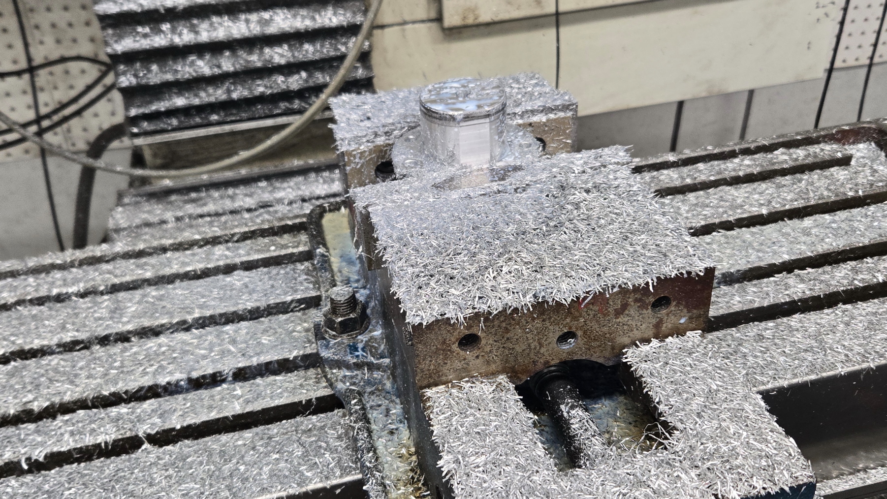
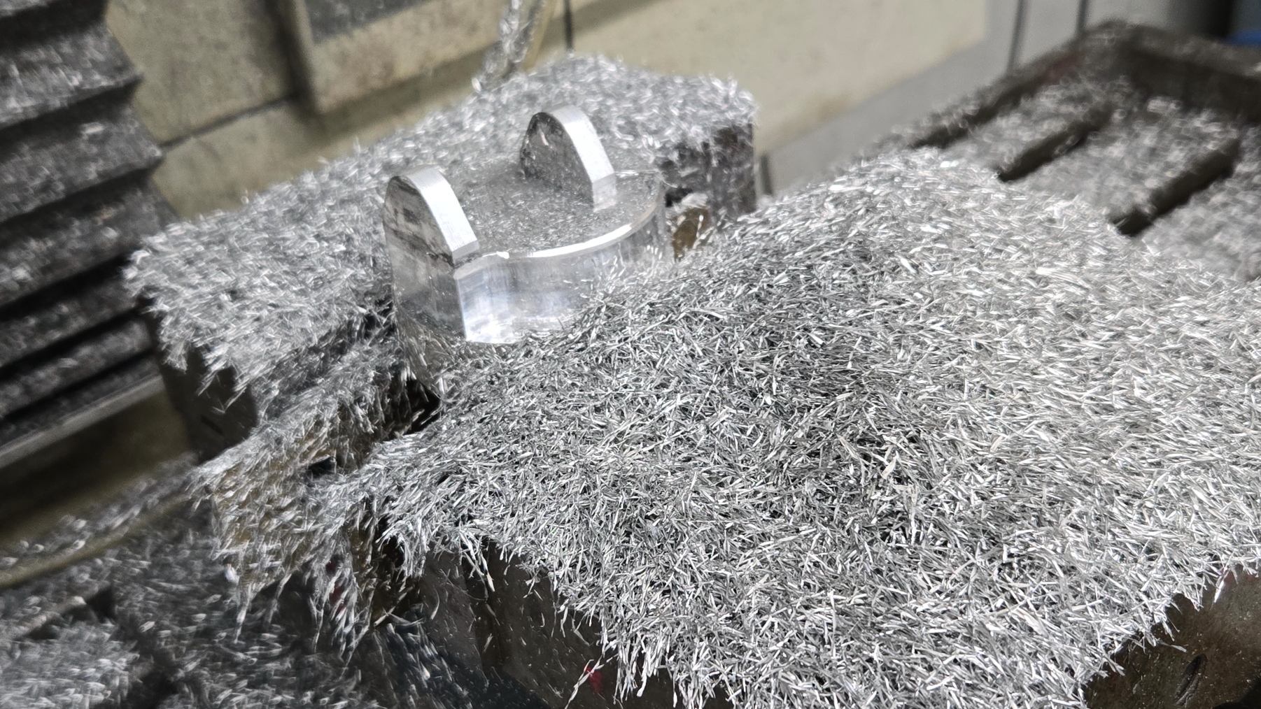
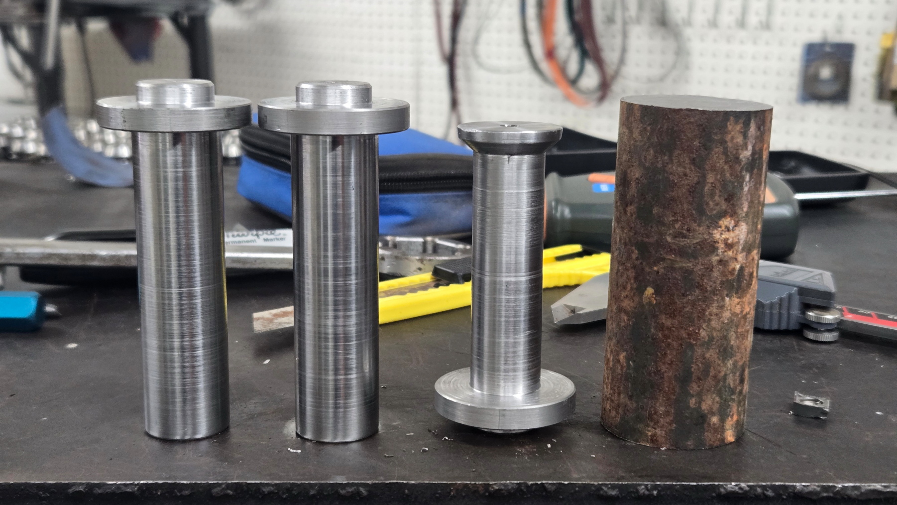
Op 2 mess on the swingarm mounts.
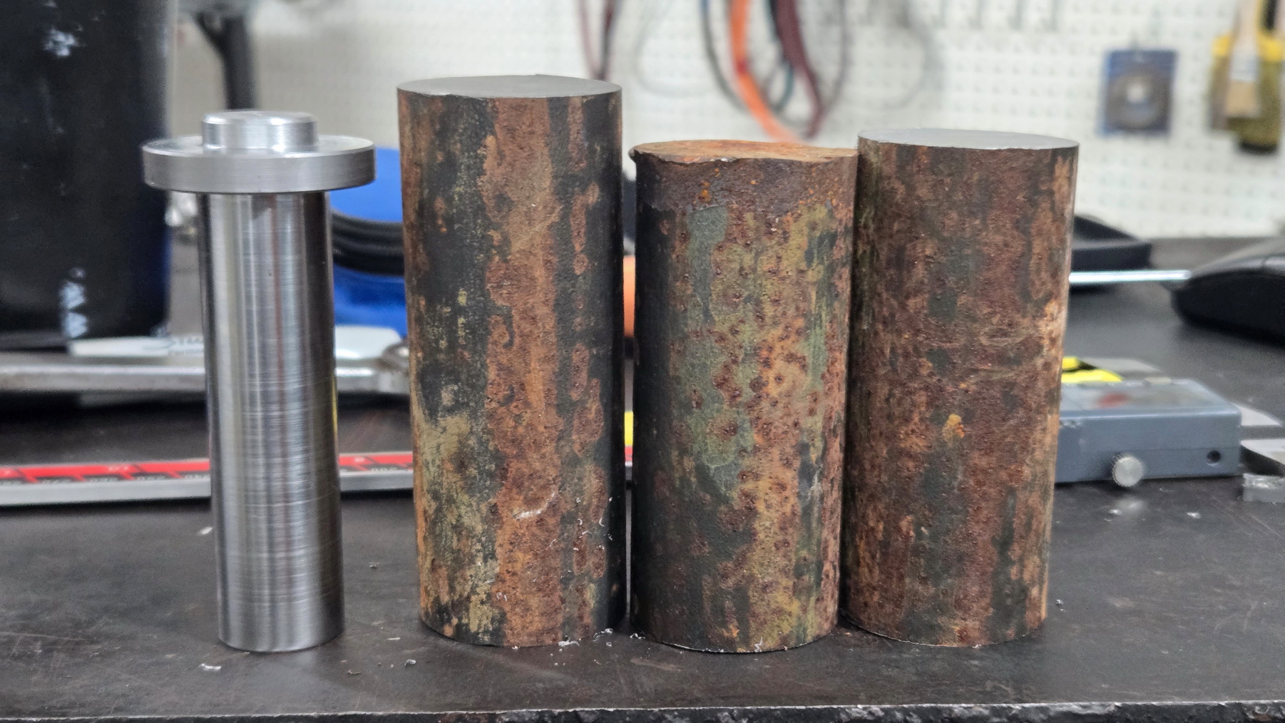
Swingarm Mount 10
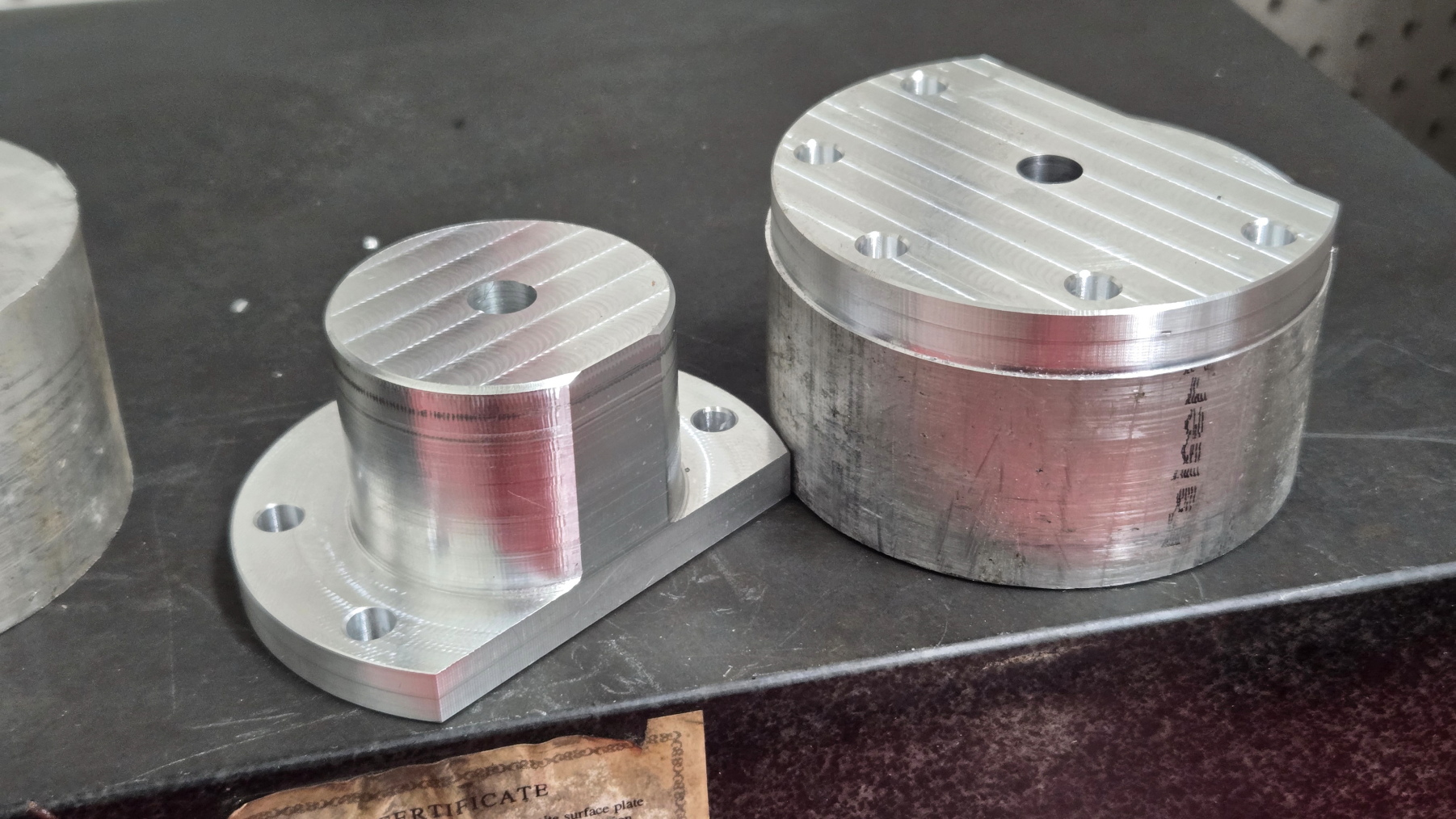
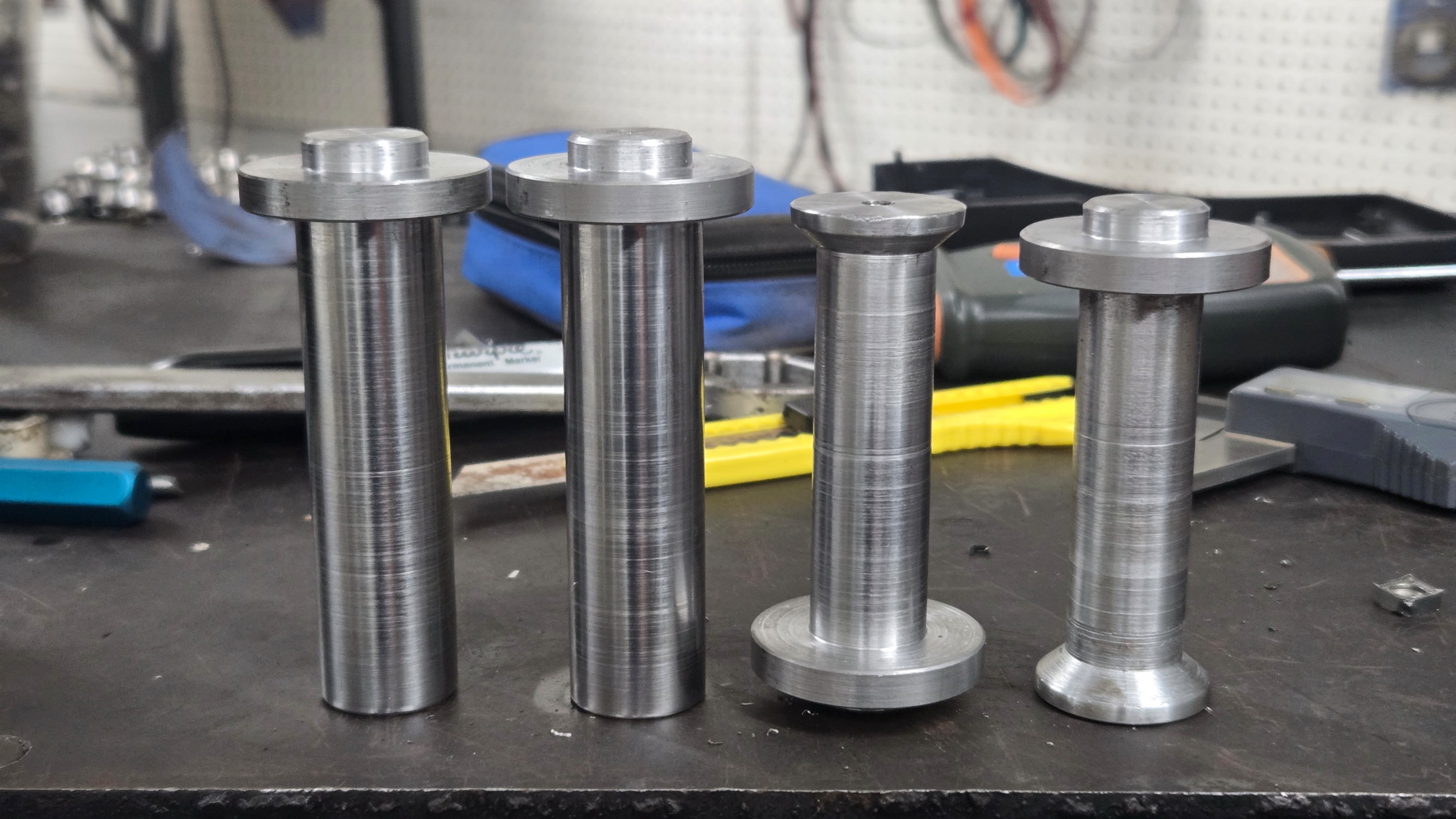
Op 1 vs 2 on the swingarm mounts.

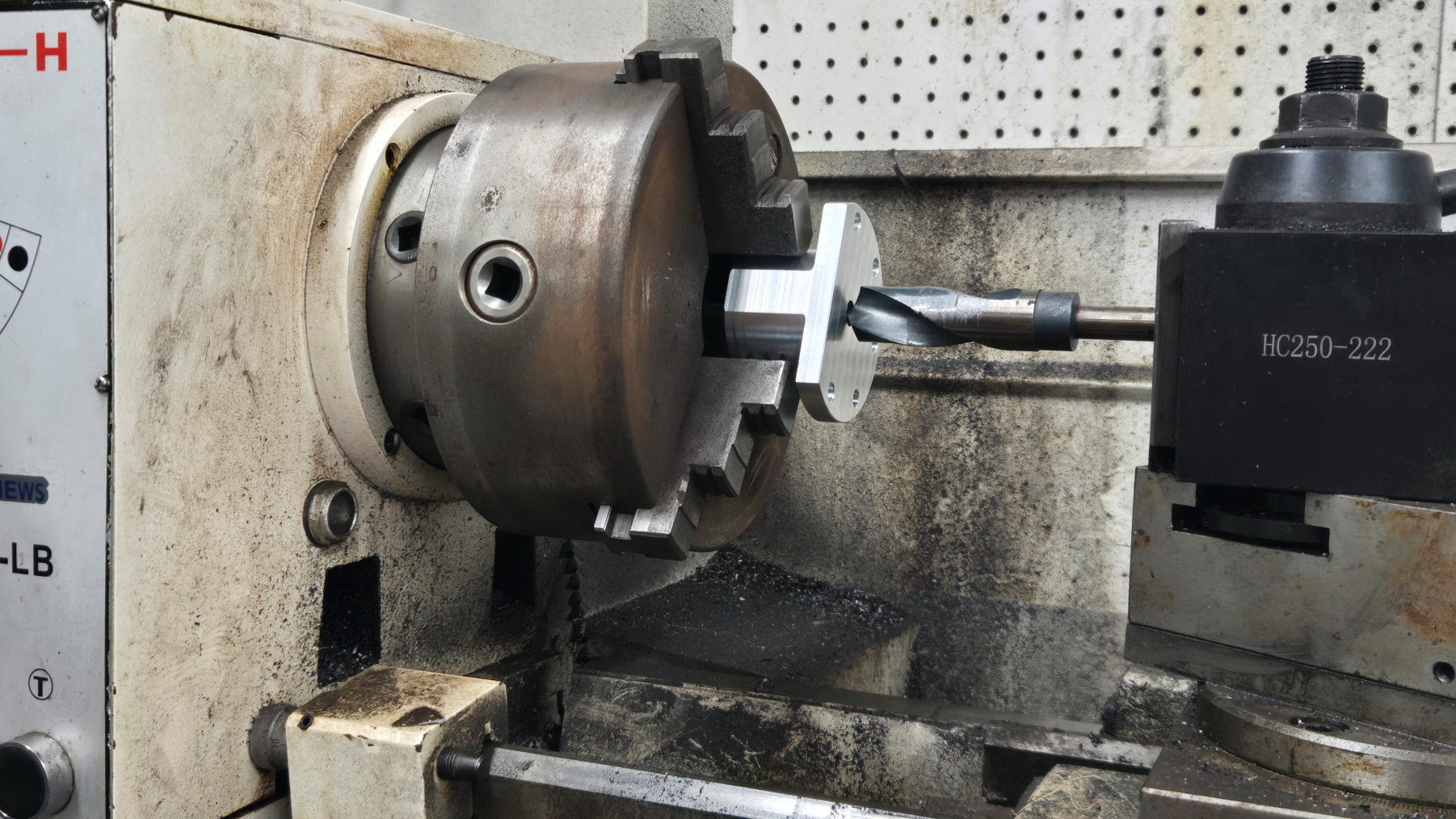
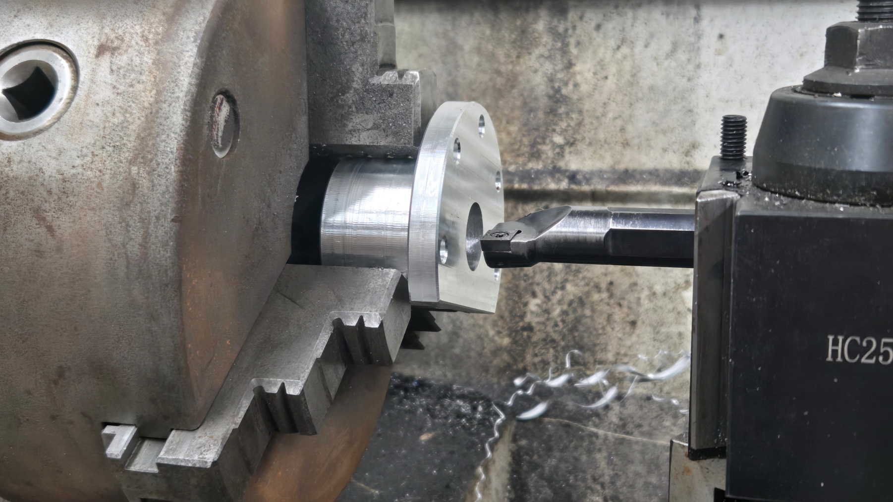
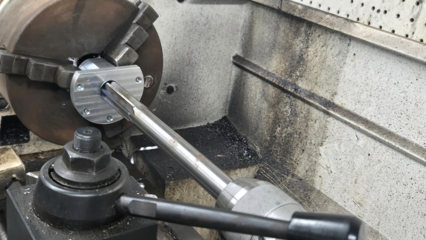
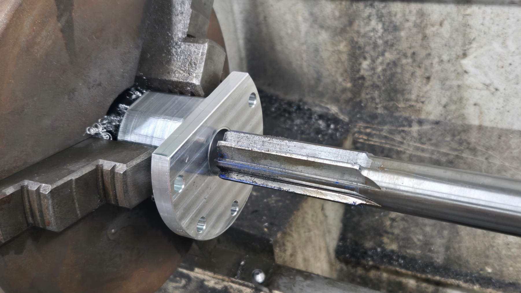
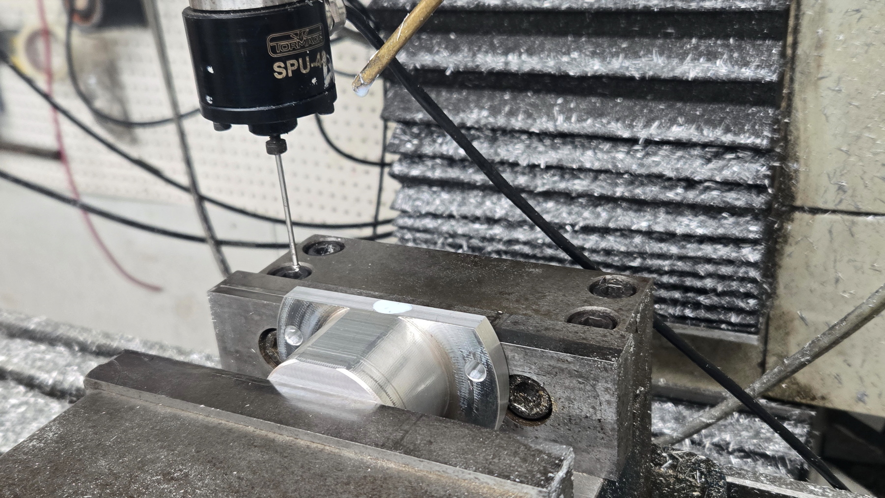
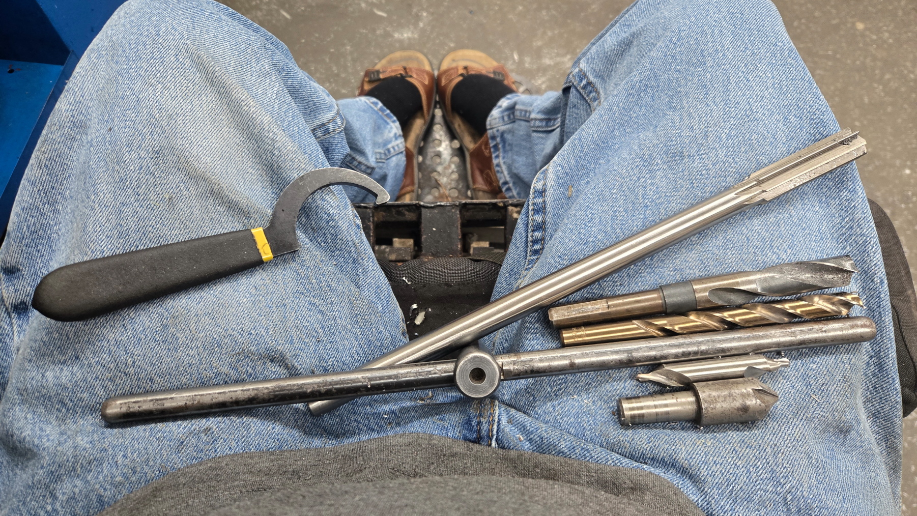
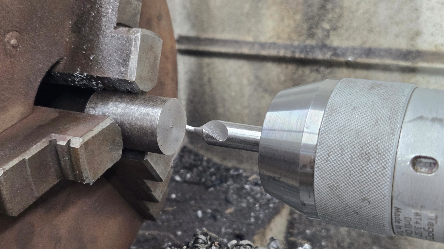
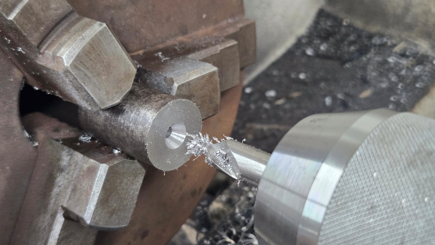
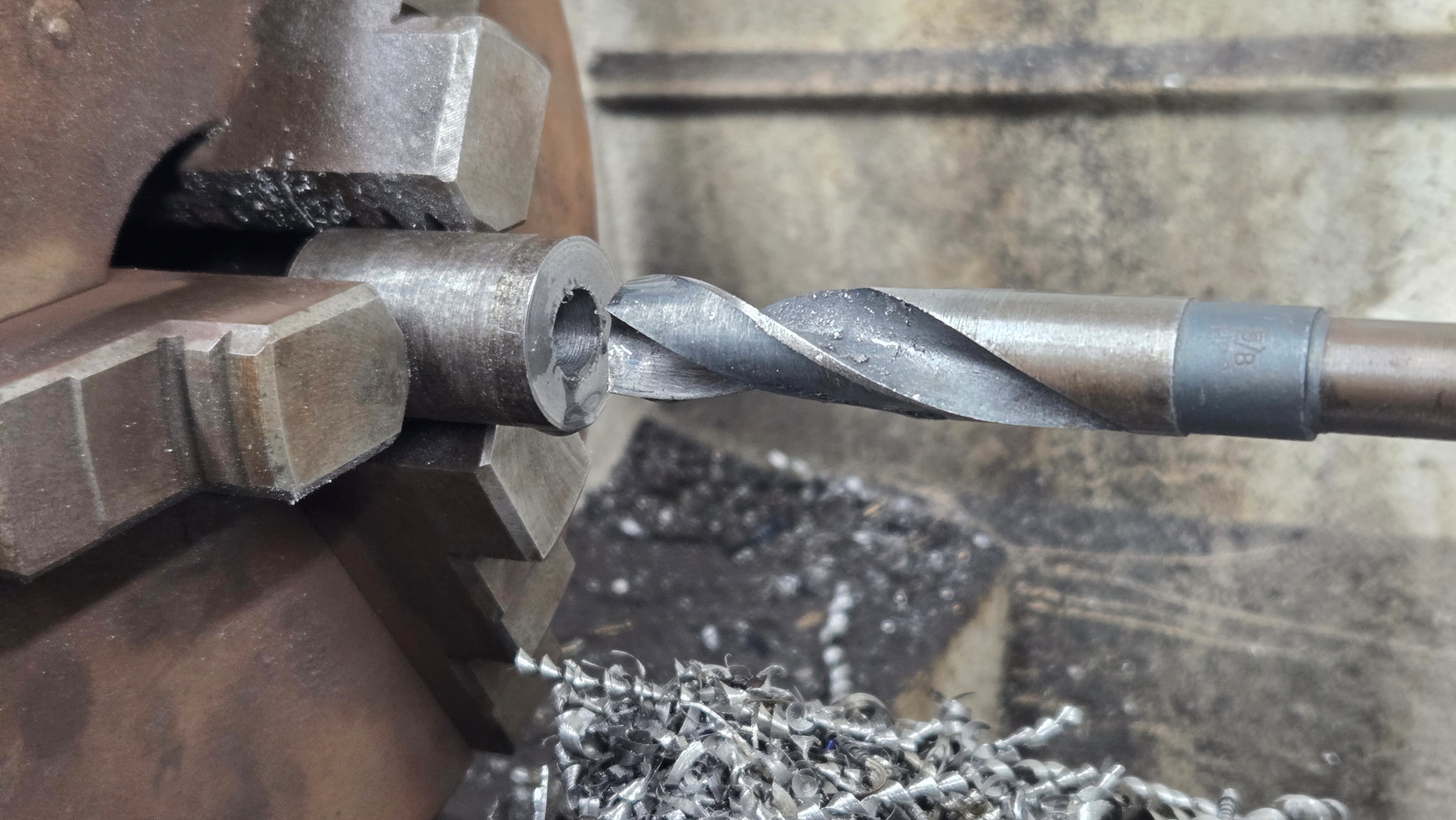
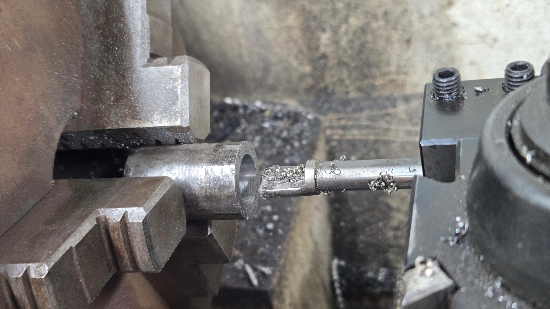
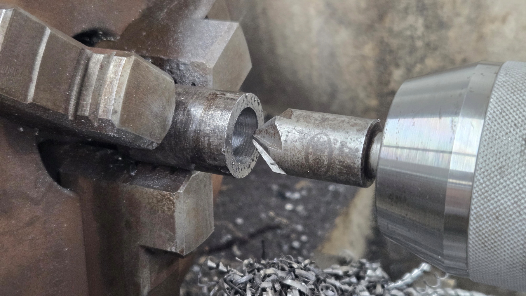
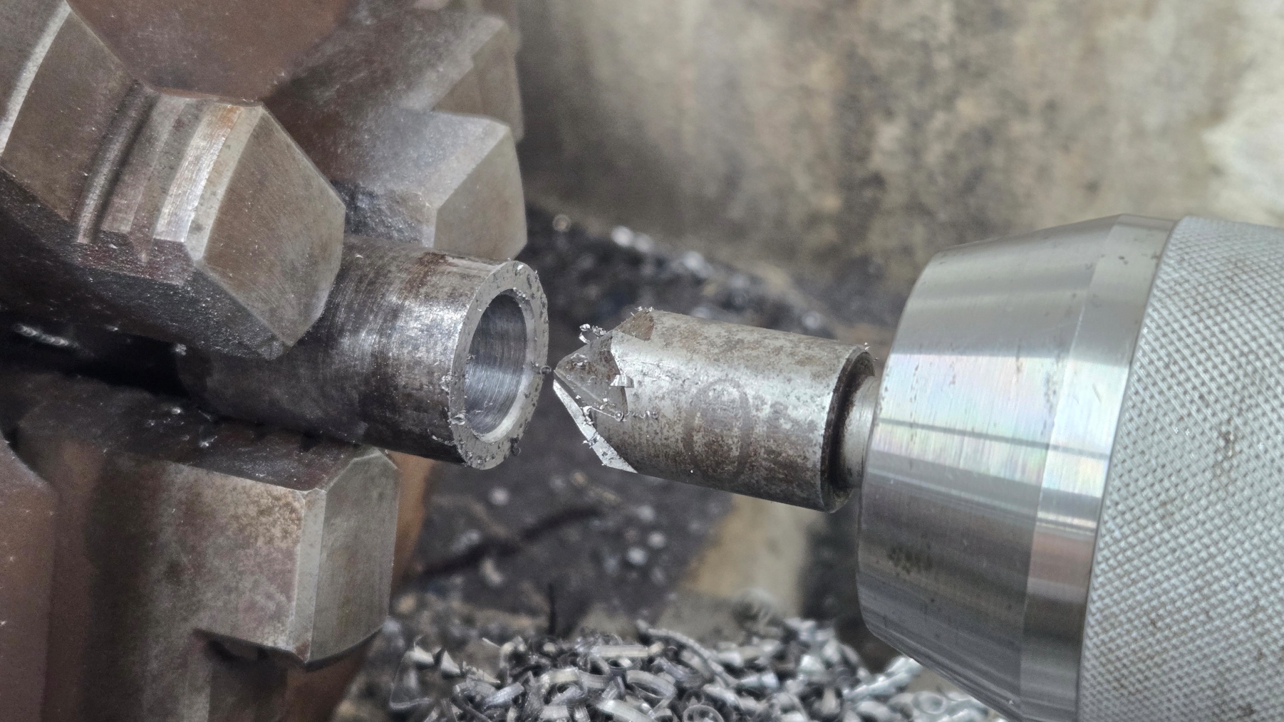
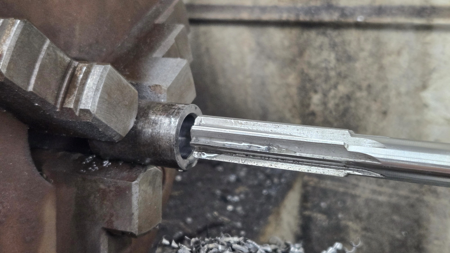
After op 1 and op 2 on the CNC machine they go back in the manual lathe to have the hole for the swingarm axle bored.  This could be done on the CNC as well, but the tools are long and it takes a while to setup and program for each tool.  I'm limited on Z height in my CNC and do not want to shorten the reamer just for four parts.  If I was making 50+ then it would make sense to sacrifice an expensive reamer or purchase a dedicated one for the sake of time.  Also, reamers are finicky to get the correct dimension they're designed to cut within an acceptable tolerance and surface finish.  They are picky about the prehole size, the lead in chamfer, runout, and speed they are ran.  A few test parts would need to be ran and possibly scrapped first.  When manually using one, you can feel when they are cutting correctly and happy.  Using a boring bar to finish is even more accurate.  Not with my hands trying to measure an id though.  Lastly, they go back in the CNC for the countersunk bolt holes that retain the swingarm axle.
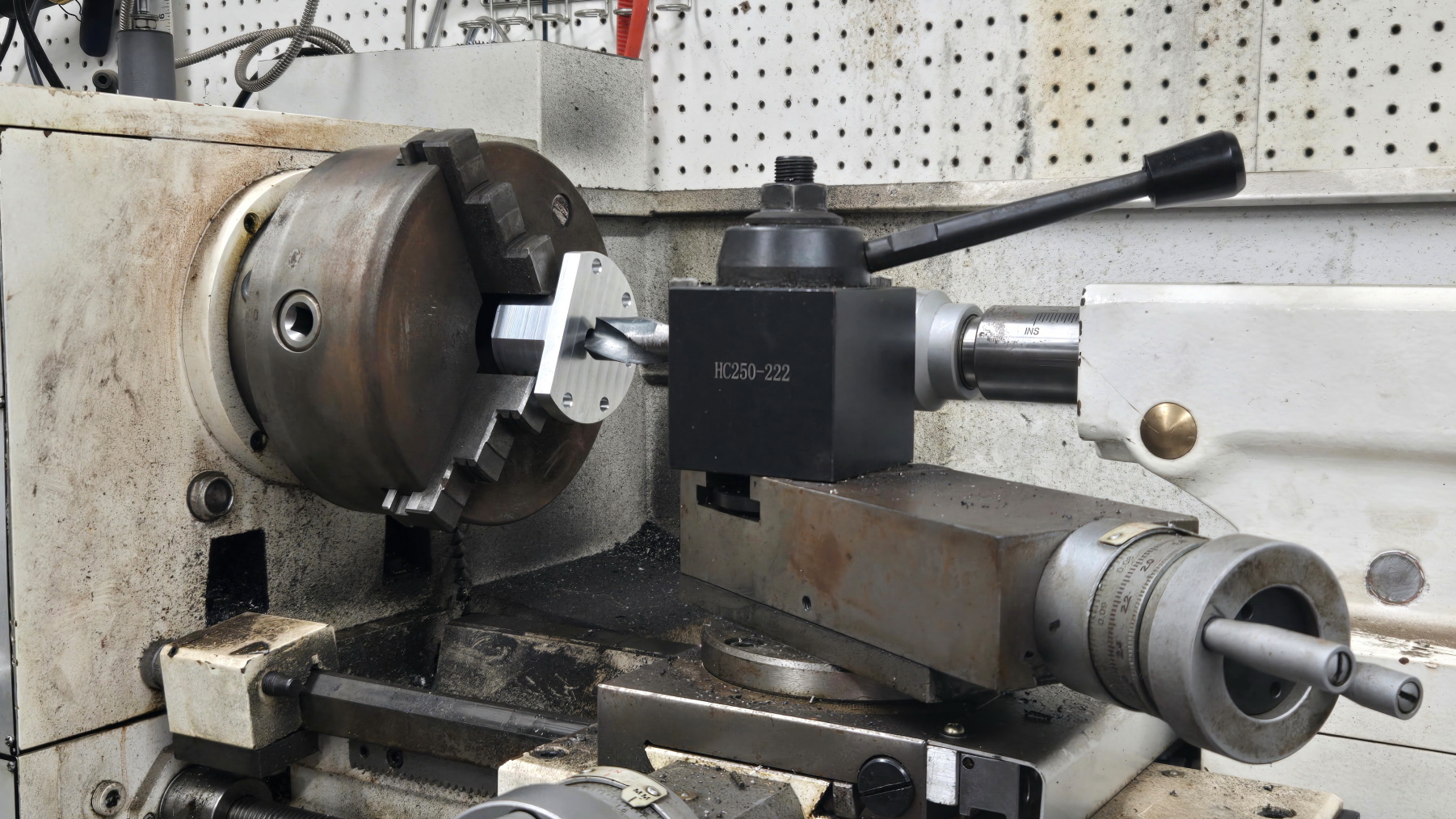
Video below machining of the swingarm mounts.
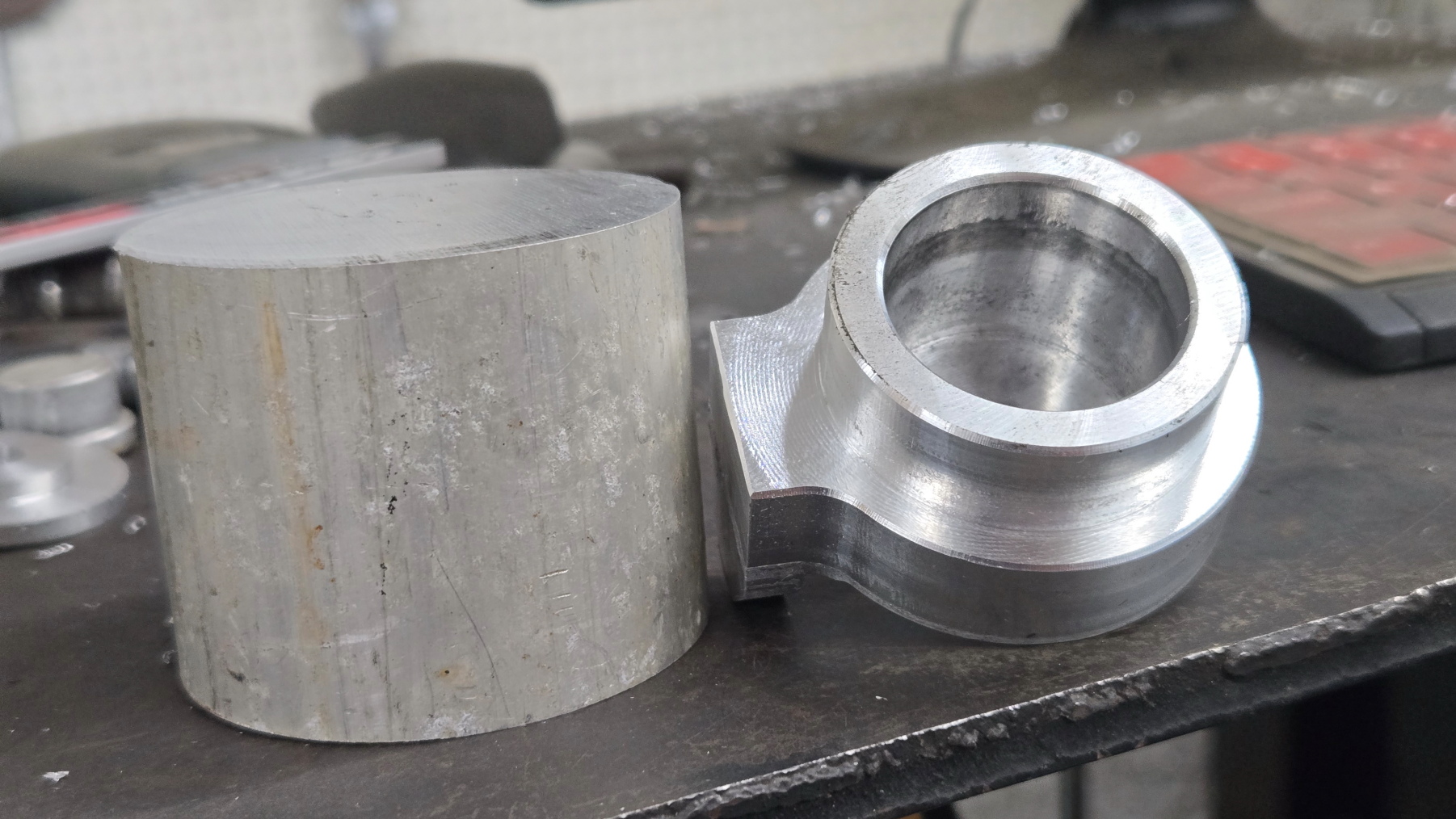
Bearing Cap 9
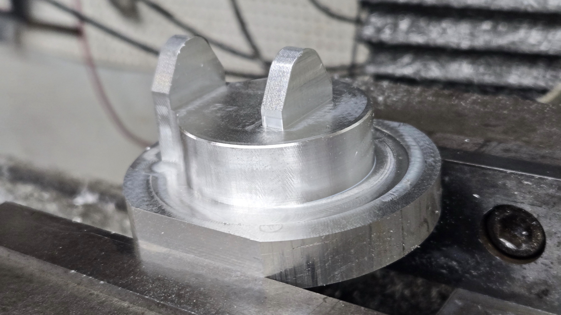
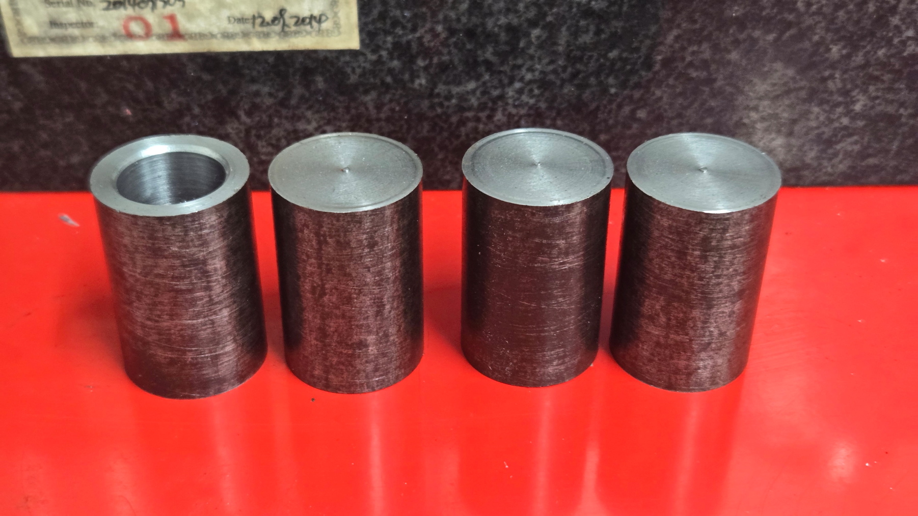
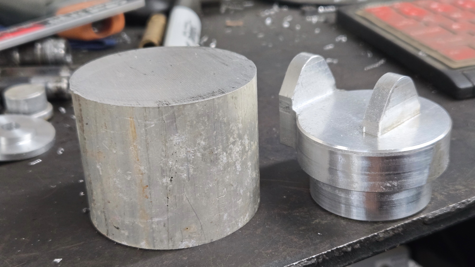
Caster barrel bearing caps. How it started vs completed except for drilling and tapping the ears for the bolt that holds the headlight.  Didn't take a picture after. 
Bearing Cap 10
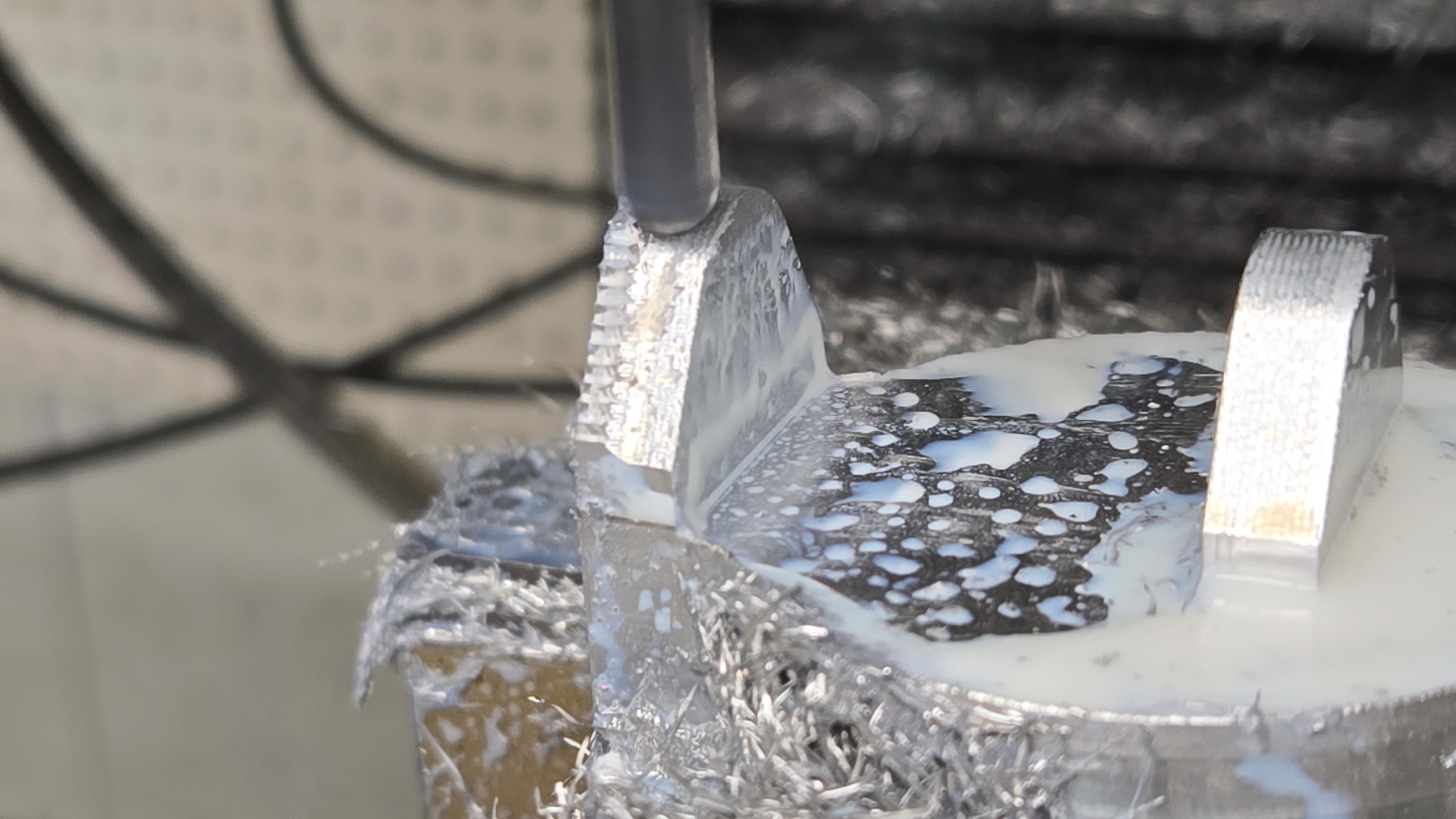
These are quite complicated and time consuming to make.

Here are a few videos of machining these.  And yes, there are different stock sizes.  I ended up making a few sets for my older chairs and used scrap.. 
Swingarm Axle 1
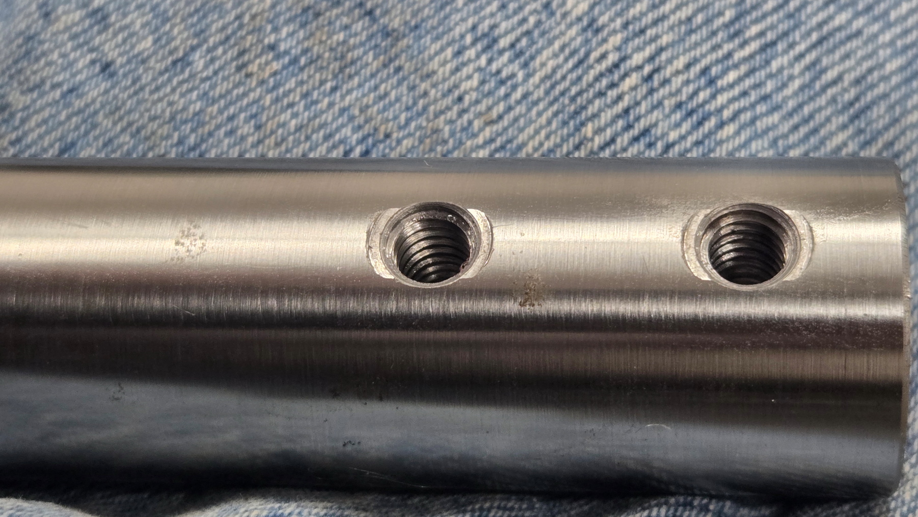
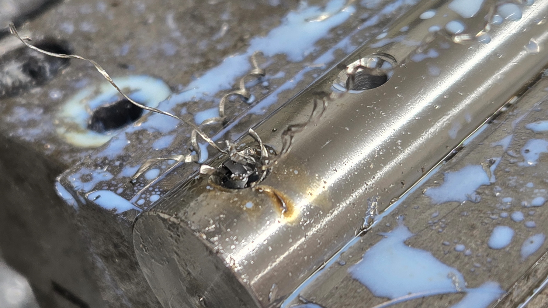
Some days you're the hammer.  Some days you're the nail.  Swingarm axles.  Everything doesn't always go correctly.  I originally made these from 304 stainless since I had a stick in stock.  Unnecessary but could make them easier to remove in the future since there would be little corrosion. 
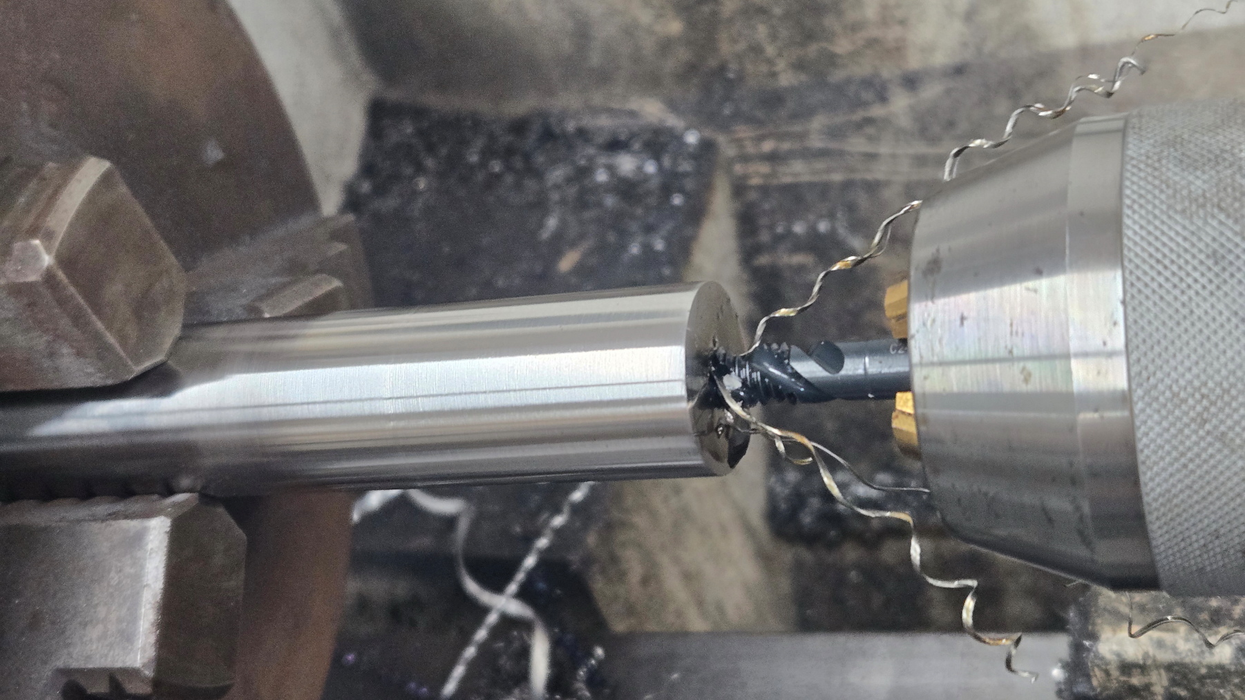
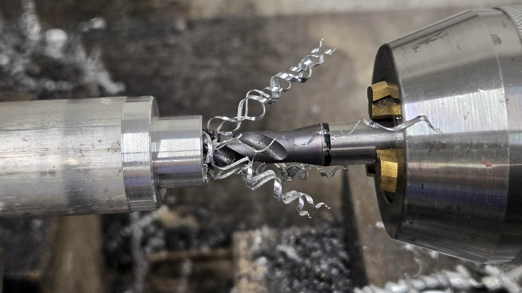
This is why machined parts from martensitic stainless steels is more expensive.  It can be hard on tooling.  This tap was not designed for stainless.  It would have not broken had I taken 10 minutes to set up the proper tool and used the proper lubricant instead of worrying about recording.
Swingarm Axle 3
Made them out of something more forgiving.  1018 steel instead of trying to overachieve.
1018 is definitely much friendlier.  4140 would have been the best choice but overkill.  These are 1 inch diameter x 4.375 inches long and supported by two 1x2x1/2 inch ball bearings.  If I manage to bend them, then I have bigger problems to worry about.
Swingarm Axle 4
Manually tapping the ends.  Good taps are expensive.  Cheap taps are the most expensive tool in the shop.  Or using the wrong tap for the application is even more expensive, as I showed above.
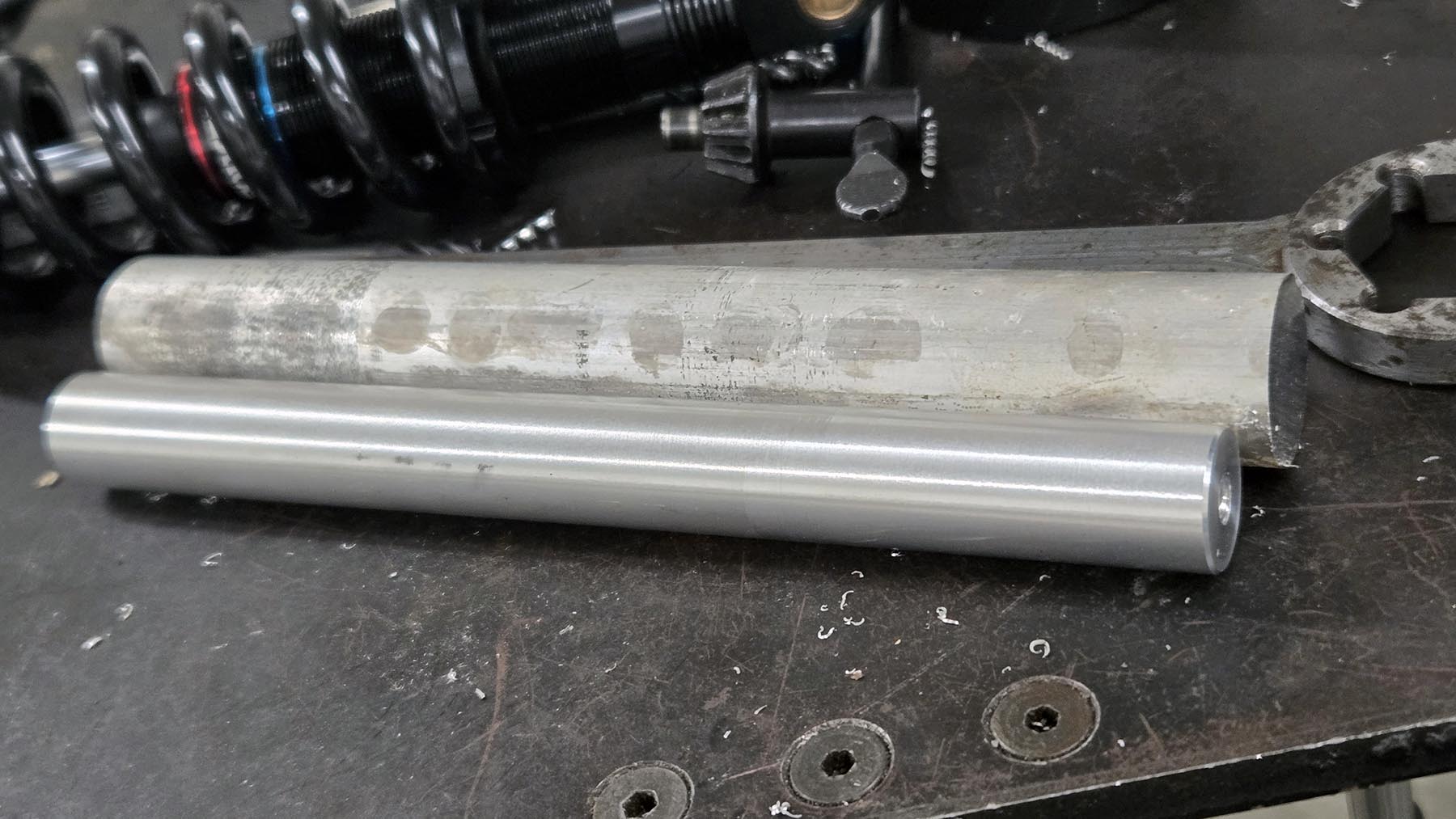
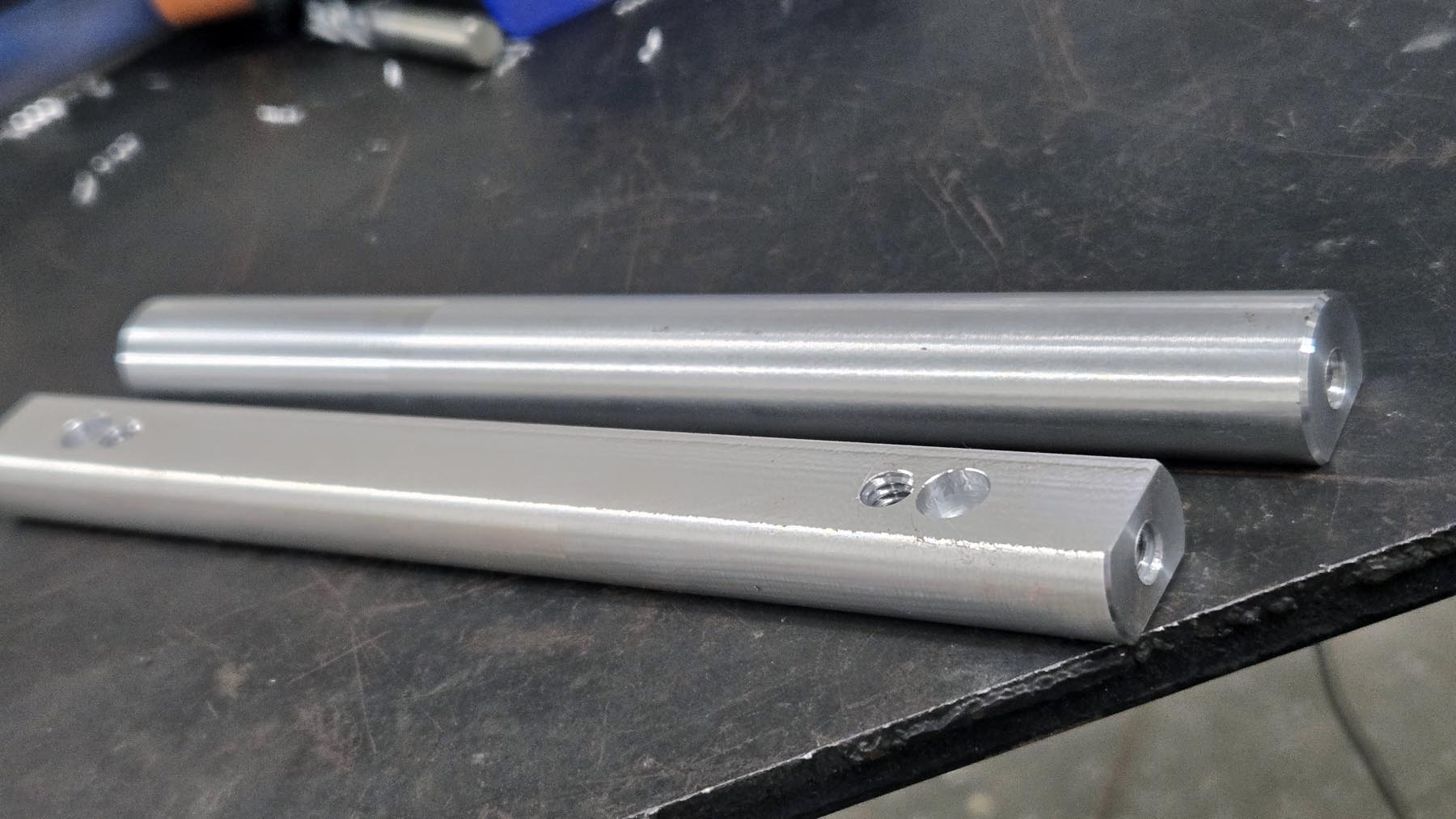
These are the docking pins for the lockdown mechanism in my vehicles (more on that device will be on another page) and the axles for the rear suspension.  Both made from 1018 steel.  Both are simple straightforward manual turning in a lathe.  The suspension axles did have a tight tolerance of .001 inch to hit on the diameter.

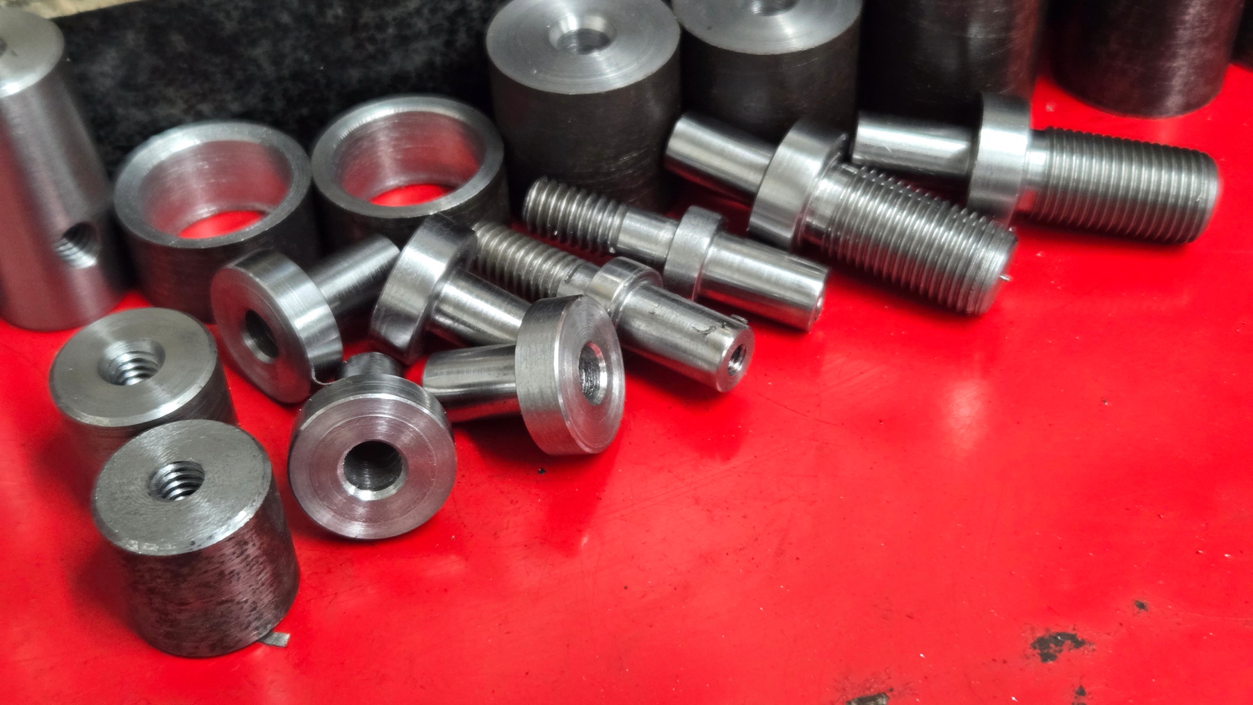
Small parts like this don't look like much but are time consuming.  Each one requires multiple tool changes.  These are some of the armrest and other small hardware parts.  Step 1 is load up my "tool cart" with what I need...

Shock Pivot 1

As parted

Shock Pivot 2
After chamfering. Always chamfer sharp edges. It makes parts better looking and more pleasurable to handle, eases assembly, and removes stress points.

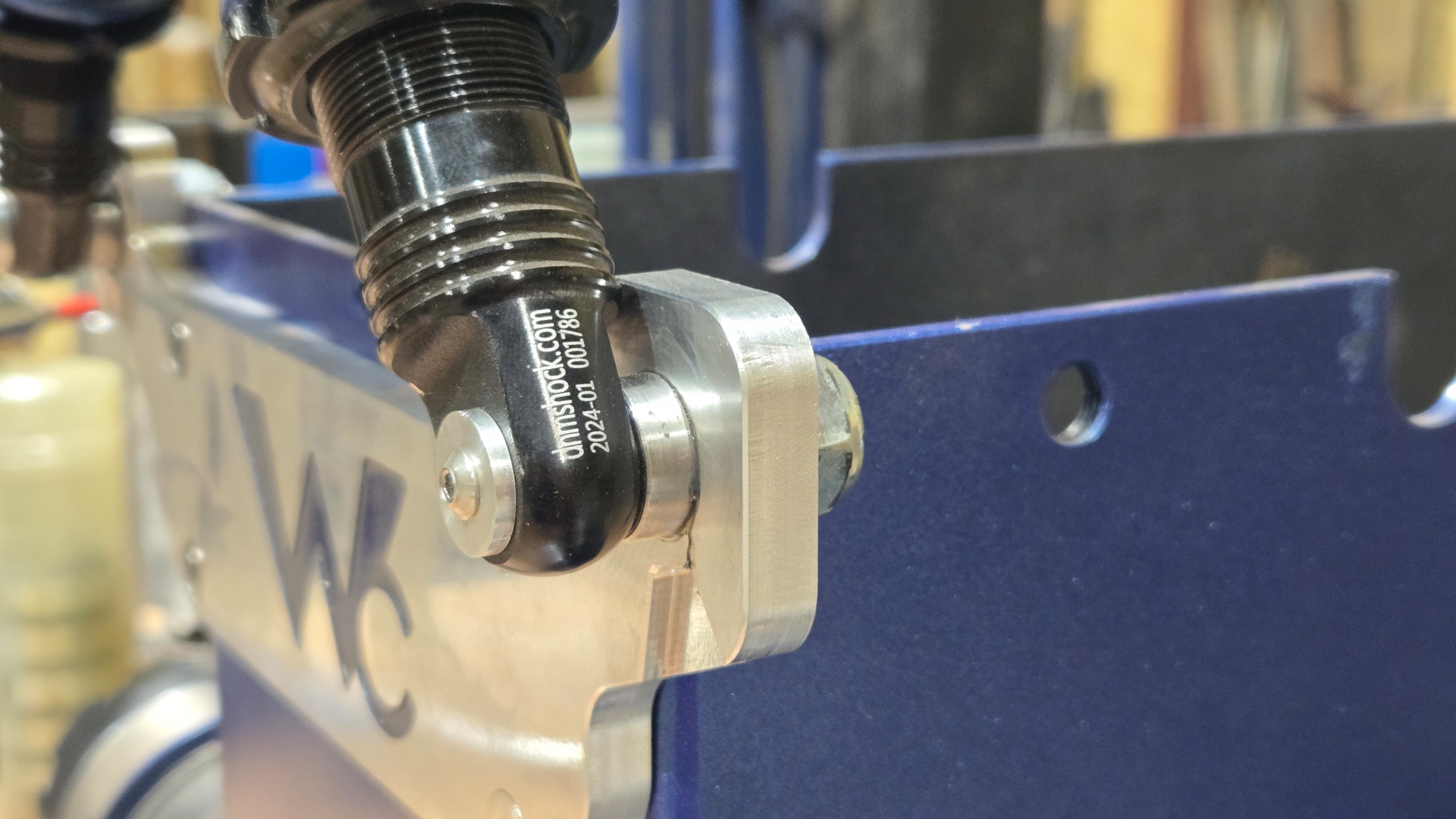
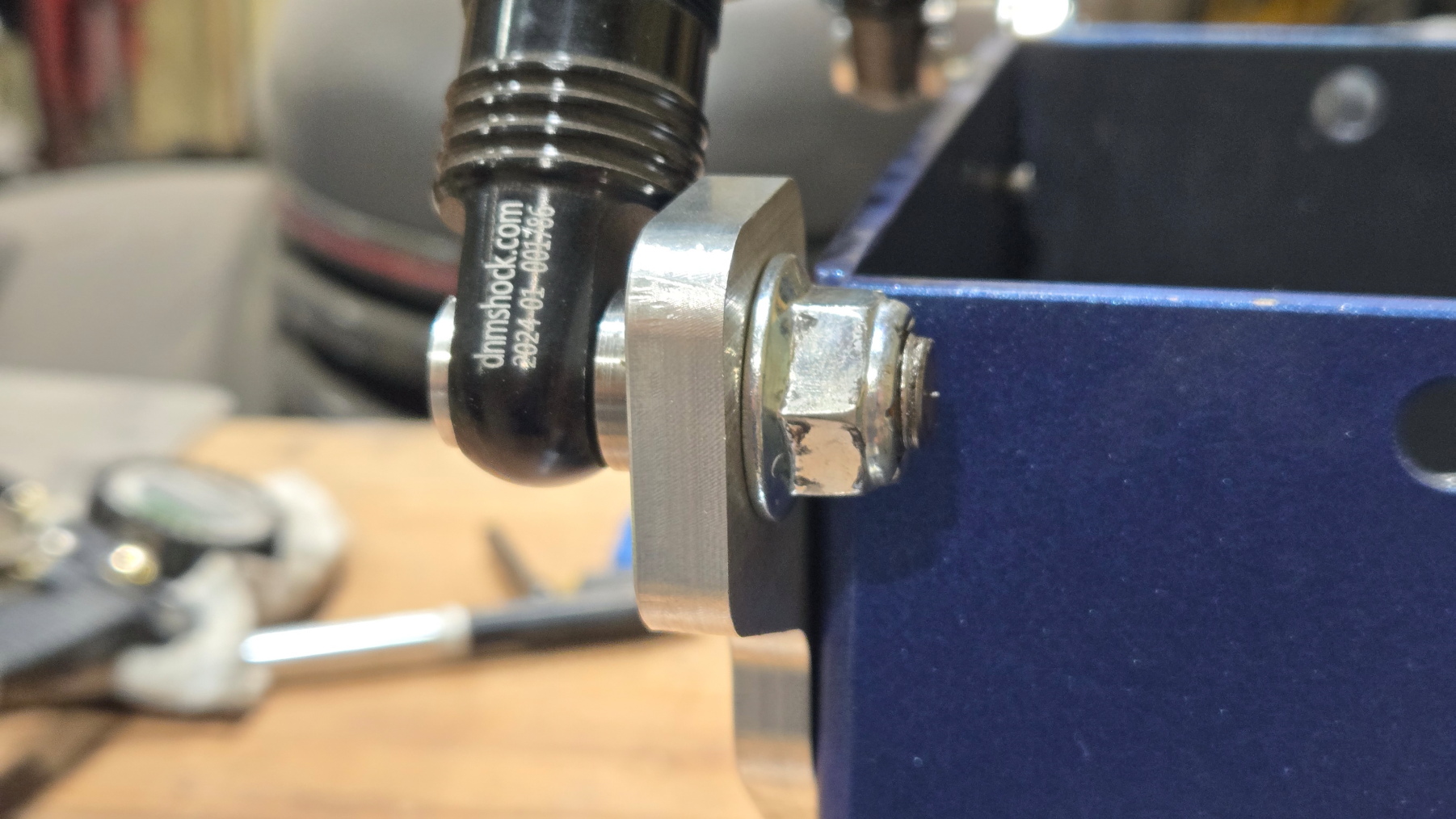
These also don't look like much but were tedious with the tight tolerances.  This is all hardware for the shocks.  They're from 1144 steel.  Quite strong and machines beautifully.  It is a great material choice when strength over price is what you need as long as you don't have to weld it.  The factory paper thin hardened steel race over an aluminum bushing sucks for this application.  They're not really designed for this type of use and load directions.  The last chair I built had gotten sloppy.  Pulled it apart and I had worn them out all the way through the bushings and the hardened steel race.  You could almost take the shocks off without removing the bolts!  After doing it this way it is still squeaky tight after several years.

Shocks 1
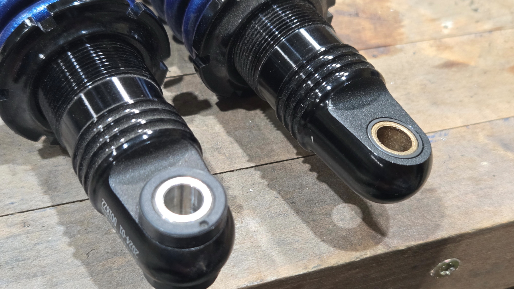
Original on the left.  Redesigned on the right.  The original aluminum bushing rotates on whatever shaft you put it on.  In my case it was grade 8 bolts.  Add a little dirt or corrosion and it doesn't take long to wear out.  The design I made uses an Oilite type bushing pressed into the housing.  It rotates on the hardened and polished pins from above. 
also made some aluminum washers to help keep out the nastiness
This is how the heel plate that goes on the back of the footrest was made.  You don't need artistic ability or steady hands when you use the correct order of operations.  Hopefully my shaky recording doesn't make you sick.
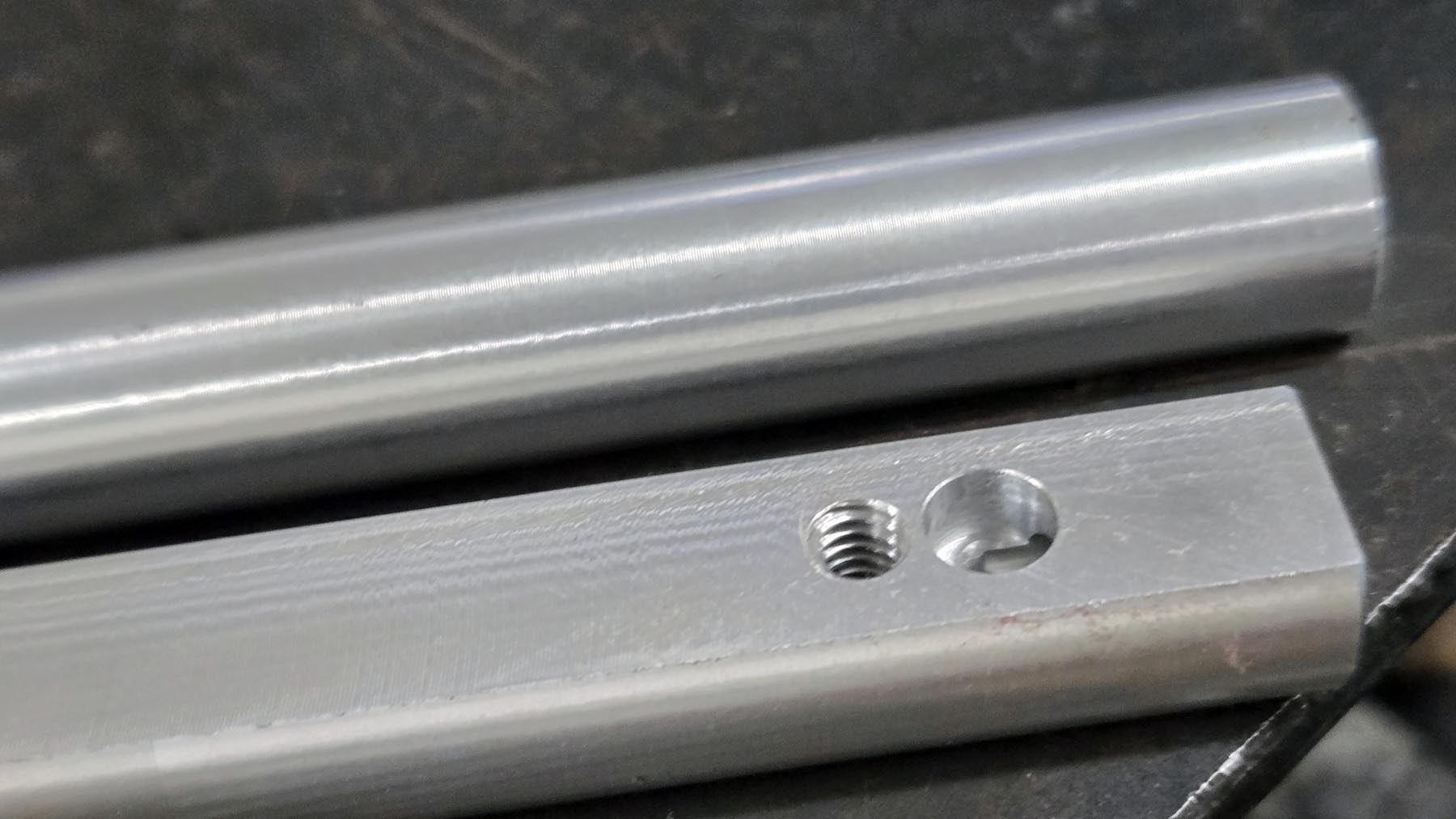
Front Cover Mounts.  The Electronics Board also mounts to the back side of thee with four standoffs.  They're inside the battery box and held on by two countersunk bolts that come in from both sides.  Not complicated to make nor require great precision.  Just a bit time consuming because so many steps and different setups required in both the lathe and mill.

Pipe Caps 1
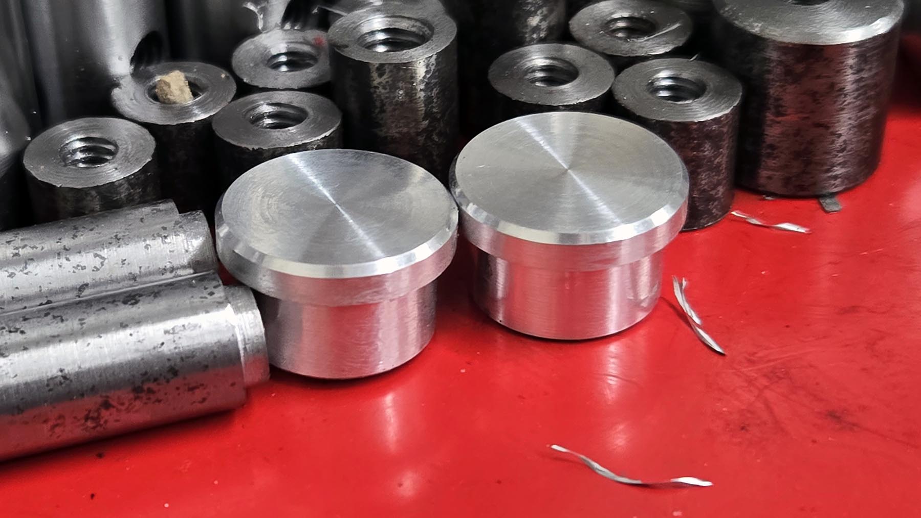
Pipe Caps to go in the top of the Uprights.  Simple lathe turned parts.  Not absolutely necessary but gives a finished appearance, helps stop scratching arms on the end of the uprights, and prevents kids and coworkers from dropping things into the hollow upright tubes.
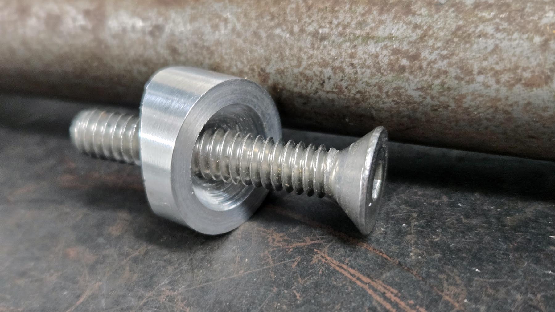
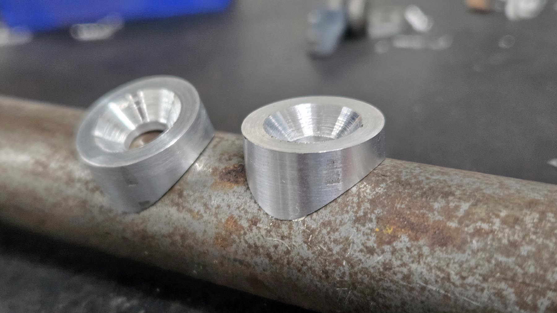
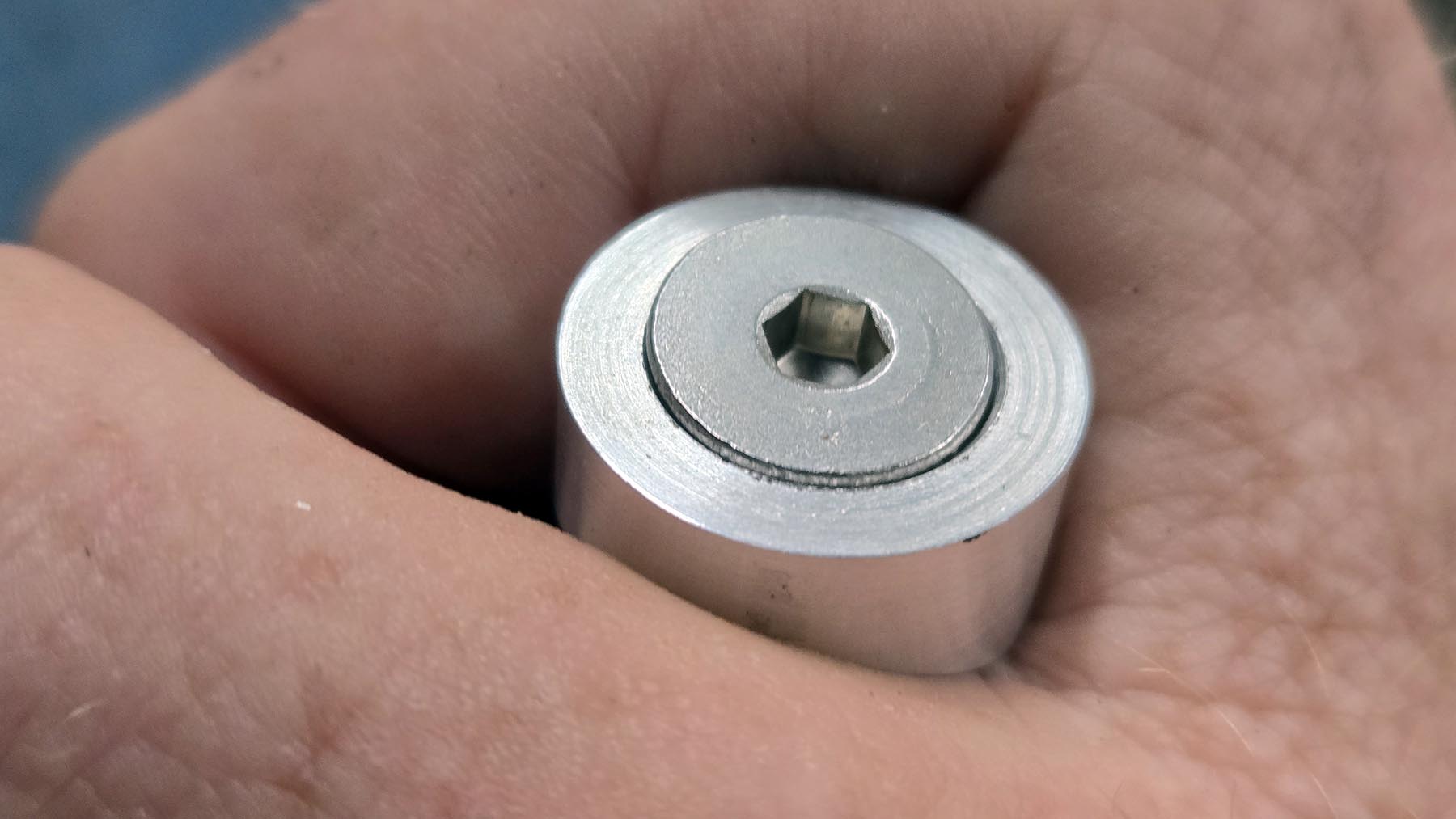
Little things like this go a long way into adding to the total polished feel of the finished product.  Flat or countersunk bolts don't really like to be tightened against a rounded surface.  These bolts go through DOM round tube to hold the two Armrest Mounts in.  These countersunk washers give the tapered head something to tighten properly against as well as look good.

Joystick Swivel 1
Joystick Swivel Mount.  This allows the joystick to swing about 140 degrees.  Three belleville washers (conical springs) go under the cap.  Tension can be adjusted by adding/removing a washer or using different rate washers.