Battery build
Most all large powerchairs use a pair of 12v lead chemistry based gel or agm type batteries wired in series to create a 24v system. This has been the norm since the 1970's. Lead is simply unsuitable for this application for a variety of reasons. The main three reasons are energy density, peukert effect, and lifespan.
Energy Density: This is basically the amount of electric potential a battery can store in a given volume or weight. You can store roughly 40 watt hours (Wh) of energy in one kilogram of a HEALTHY lead acid type battery. Slightly less in gel types. That's roughly 60 Wh per liter of volume.
Peukert Effect: The change in capacity based on the rate of discharge. In short, the faster you try to pull energy from a battery, the less energy it can provide.. This is why when your car battery is "dead" and won't start, the headlights still shine bright then get more dim as you try to crank it. There may still be 300 Wh of energy left in your 800 Wh battery, but it can only provide 100 watts due to the capacity being low. Your headlights may only be drawing 5 amps (about 60 watts), which it can output. Your starter needs 200 amps (about 2400 watts). The energy is there, it just can't escape fast enough. As a lead battery discharges the internal plates become covered in lead sulphate, which does not conduct electricity. The more the plates are covered, the less of the energy creating chemical reaction can occur. It's like drinking a bottle of water where the hole gets smaller as the bottle empties. You can eventually get all of the water. It will just come out slower and slower as the water level decreases. This application consumes power in big doses, not a steady pull. Lead batteries cannot provide the big gulps of energy once they are discharged about 40%. Basically half or more of the stored energy is unusable. A 70ah lead chemistry battery only has about 35 to 40ah of usable capacity, and that's when it is healthy.
Lifespan: Lead is typically good for 200 to 500 charge cycles. It can vary greatly by the amount it is discharged and how it is recharged. Lead is only happy when full. It deteriorates as it generates energy from creating lead sulphate. Each time you recharge, the lead sulphate breaks off and is absorbed into the electrolyte. Some of it remains stuck on the plates along with tiny bits of lead breaking away. The deeper you discharge a lead battery the more this happens.
There are many types of lithium batteries. All are not created equal. The most common chemistry is LiCoO2, or lithium cobalt. These are found in everything from cellphones to power tools to laptops. They have good energy density at around 190 Wh per kilogram and 550 Wh per liter. They don't suffer from the peukert effect, can be recharged 300 to 500 times, and can put out the energy required for this application when built with a large enough capacity. They have one huge disadvantage that completely rules them out: Fire. When shorted internally they generate heat proportional to their size. A battery big enough for a powerchair could create a massive fireball if damaged. Not good when you can't run away or it is parked in your closet. That's why their size (capacity in Wh) is limited on airplanes. The second most common is Lipo or lithium polymer. That's what you will find in RC cars, drones, and small jump starters for cars. They vary wildly in energy density, but some variants are over 250 Wh per kilogram and 700 Wh per liter. They can output incredible amounts of energy without damaging the cells, even at small capacity sizes. Unfortunately, they start deteriorating after 30 to 75 charge cycles and create a massive fireball when they get angry.
The only suitable chemistry currently available to consumers is LiFePO4, or lithium iron phosphate. You'll find these batteries in energy storage solutions, solar, and golf carts. They are around 140 Wh per kilogram and 350 Wh per liter, depending on construction type. They don't suffer from the peukert effect, can be recharged 3,000 times or more, and have become quite cheap as they gain popularity and patents expire. They also do not burn when damaged or shorted internally. They only release white smoke, smell bad, and drain a small amount of whatever liquid electrolyte the manufacturer used. The main downside to them is the complication. They must be kept between charge amounts to avoid damage. Discharging them down below 2.5 volts per cell can cause damage that can sometimes not be repaired. They also do not like to be full for more than a few hours. They should be stored between 30 and 80% charged. The key to building a battery pack that will outlive most breeds of cats is to assemble it from high quality fully charged cells, never discharge it more than 90%, only balance it while charging once the cells are over 3.45 volts, and build it with a large enough capacity to where you never charge it over .5C nor discharge over 2C. C = capacity. For a 100ah pack you don't want to pull more than 200 amps or charge faster than 50 amps.
LiFePO4 batteries also have a flat discharge curve. This means you cannot know how much energy is left in the battery based on its voltage. This also means it is pointless to try to balance them below 3.45v per cell. You will actually unbalance the pack if you do. This is why off-the-shelf BMS (Battery Management Systems) that are not programmable cannot be used. The voltage of a pack at 45% is the same as a pack at 99%. They cause far more harm than good and waste energy by moving it around from cell to cell all of the time trying to keep them balanced.
I highly suggest purchasing cells with stud terminals. You can cut them off shorter after assembly if needed. They're usually aluminum. Cells that take bolts are asking for trouble. The holes are shallow, requiring near exact length bolts or stacking washers to engage enough threads without bottoming out. Several cells will have thicker wire lugs when you make the final connections. So, they'll need slightly longer bolts. The holes are also soft aluminum and easy to strip out. I have built a few packs that used bolts. Never again.

Apply an ACCURATE fixed voltage of 3.6v and wait. No more. No less. Do not apply 3.65 or 3.7v even if the manufacturer says it is ok. That will decrease charge time so they can publish inflated figures. This is not the time to save an hour or two. Be patient. This will take a while. Each of these cells is 100ah. There are 14 connected here in parallel to equalize and later become a 14S pack. P = parallel and adds capacity. S = series and adds voltage. Technically, they are currently connected in a 14P1S configuration. The 1 is ASSumed if not written. So, just 14P. Each cell is 100ah. Capacity in amp hours x voltage = watt hours. That's 1400ah of energy stored but only at 3.32 volts, totaling about 4600 watt hours of power output.
They can only be self balanced like this when connected in parallel. If they are 50% full then 700ah of energy must be returned to fill them. This charger is set to 10 amps. That means it can return 10ah of energy per hour. 700/10=70. It will take about 70 hours to reach full if they are at 50%, plus a few hours due to efficiency losses. They could be 30%. That would be 98 hours. No way to know. Just let them cook until they rise to 3.6v and the current flow drops to a few mV. Any DC charger that can output 3.6v VERY ACCURATELY and up to 50amps or so is fine for this step if your wires and connections can handle it. Do not exceed about .3C for regular daily charging, where C is capacity. This is currently configured as a 1400ah pack. 1400ah x .3 = 420 amps. You won't hurt them charging at 50 amps in this configuration. Again, be patient. 10 amps is fine, just slower.

The above steps are not open for debate. Any experienced pack builder will agree. The remainder is different. Ask ten different builders how to do this and you will get ten different answers. I made custom bus bars for this particular pack from 101 oxygen free copper flat bar. I did not like the ones that came with these cells. Unfortunately, uncoated copper oxidizes rather quickly. All bus bars were sanded minutes before assembly. A thick layer of heavy duty conductive grease was applied to protect them. Messy but affective. The pack in this picture was built in 2019 and still in daily service. Last time I uncovered one of these packs just to check the grease was still doing its thing with shiny unoxidized copper underneath.
I have built quite a few using the supplied zinc coated copper bus bars. They work well also as long as they are good quality. Shake them all together in a bag then rub with your fingers. Trash them if the zinc flakes off. Confirm that they are zinc coated copper and not aluminum. You can tell from the weight, feel, and by filing a corner to see if it's copper underneath. I used them on the last few packs. I did not take pictures and they're already installed. Flexible bus bars are also available. I suggest using those if you cannot secure your pack to where it is completely rigid. Any pressure on the studs can risk pulling it loose from inside the cell.
Do NOT tighten any nuts until the pack is tightly bound together and can NOT flex! You do not want the studs under lateral pressure. Also put thin plastic spacers between each cell. The blue coating is thin and wears away easily. The metal casing underneath is conductive. You can see the yellow spacers in the previous photo. Most cells come with spacer sheets. You can use a thick waxed paper if yours do not.

High quality low resistance connections are imperative. Buy the proper crimp tool for your terminals and apply enough solder, using flux, to seal the wire and ensure low impedance.


This is now a 14S pack. To know the final output voltage you multiply the S number x the voltage of each cell. Each LiFePO4 cell is 3.32v nominal. 14 x 3.32 = about 46.5. The watt hours are still about the same 4,600, but at 46.5v and 100ah instead of 3.32v and 1400ah from the above initial charging and balancing configuration. Same cells. Only how they were connected together changed.
Wrap the cells tightly. Kapton or packing tape works well. Any heat resistant tape that is not flexible and doesn't have a soft thick adhesive will do the job. Do not use electrical or duct tape. That's asking for a mess later on.


Finish placing all of your wires and connections. All nuts are still loose. The big red wire is my main positive. The black thing is the BMS. I use a JKBMS. It is the only one I have found that is suitable. More on that later. Don't buy a knockoff. You're better off not using a BMS at all and using a balance charger (if you can find one) than going cheap here. I did that for over a decade, but that's another story and not necessary anymore. The red thing is a part I 3d printed in order to have one main positive and one main negative connection. Once completed, nothing else on the pack will ever be touched again. The pack will most likely outlive the rest of the chair.


Wrap the pack again with tape once all components are in place. Don't be prissy with it. Lift one end. If it flexes any at all along the length you failed. Wrap tighter. Lift both ends one at a time. Lift each corner. It should feel like a solid chunk of wood. Only after there is zero flex and all wires are secured can you tighten the nuts. Clean the threads with alcohol and use threadlocker. Torque them to whatever max torque spec your cell manufacturer recommends. Some people prefer to use washers under the nuts. I typically use stainless locking flange nuts. If your wires are properly secured they will never move and loosen a nut, negating washers.
Optional but recommended. I cut a piece of 1/32" thick Buna N rubber sheet large enough to wrap around the sides of the pack and back. Sit the pack on the center of the sheet and now you have something to lift it with and drop into the chair. Fold each side of the rubber sheet over the top to protect the studs from anything that will cause shorts since they are all hot. This also protects the delicate corners of the cells. You can see the red 3d printed piece is all that is visible. After making the main connections here, another 3d printed protective cover will go on. The inside of the chair frame is also liberally coated with spray electrical tape.


I drew this wiring diagram for the battery pack. It looks more daunting than it really is. This applies to my exact setup only. There are many different configurations possible. Youtube is full of tutorials, both good and bad, on how to connect LiFePO4 packs of different voltages.
The chair has MANY more wires. This is for the battery pack only. Some components share these connections. This is why I make the main battery connector and place it on the front of the pack. No need to ever touch the actual pack connections once installed. I'm no electrical engineer. This is for reference only. Don't blame me if you follow along and your dog gets worms.
The two green connections are optional. If you use them, I suggest running them through a 200amp capable disconnect switch. These bypass the BMS. They allow you to power the chair and charge it (but not balance) temporarily in case the BMS ever fails. Flip the switch and you're back rolling. If they are connected all the time then the BMS can't accurately show you the capacity remaining in the pack, live current draw, charge current, or regen.

Charging could not be simpler once everything is set up properly. Any polarized bipole connector such as XT50 or Anderson will work as long as it can handle the current and you can physically use it. I've been using these for a decade with no issues. They're made for trolling motors and solar power storage solutions. They're cheap, robust, waterproof as long as you use the rubber covers, available in different current ratings, and somewhat easy to connect/disconnect.


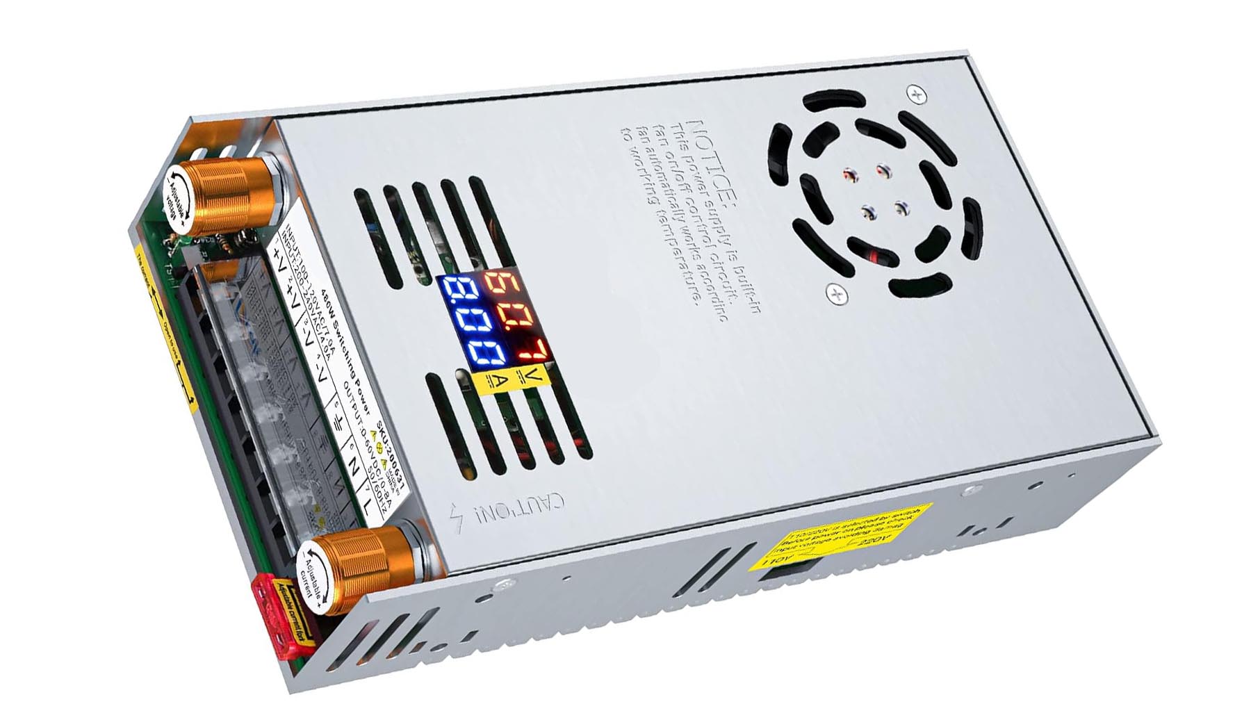
Any power supply capable of outputting the current you want and 1 to 5 volts over the FULLY CHARGED actual pack voltage will work fine. You want something "dumb" and not a smart charger. The BMS will cut the power as needed. A 10 amp power supply is plenty for a 100ah 46.5v pack like this. At half depleted it needs 50ah of energy returned. At 10 amps it will return 10ah per hour. That's only five hours needed to recharge. Add another hour due to heat losses and balancing. This is another benefit of increasing the total system voltage.
Add in the efficiency gain of higher voltage, brushless motors, and planetary gearboxes and this 100ah battery lasts about a week of long daily use between charges. I can cut all of the grass on my rough 6 acre yard with one charge. An elaborate or expensive high power charging setup is not needed.
Follow along to the wiring page for the real headache.