
Wiring
I'll keep this page short. There's not really anything to see with photos. I drew the below wiring diagrams to aid in building the wiring harnesses prior to assembly. The key is to stay organized and use proper soldering, crimping, and strain relief techniques for safety and reliability. Troubleshooting is extremely difficult when you're questioning yourself on wiring connections. Use as few connections as possible and only use high quality connectors from reliable vendors like Digikey, Mouser, Newark, Allied, etc. Stay away from Scamazon and Fleabay knockoffs. They're not worth the small cost savings.
Only use high quality automotive grade oxygen free copper (ofc) TXL or GXL rated wires from reliable sources like Mcmaster Carr, Wirebarn, Digikey, Allied, etc. Again, stay away from the usual discount scumbags that are happy to sell you copper clad aluminum (cca) wire masquerading as something better. Use twisted pair shielded cable for the signal carrying wires like the joystick, hall sensors, and encoders. There are higher spec wires that advertise better flexibility, heat, and abrasion resistance with different insulations such as silicone. They look good on paper. I have never tested them long term. Use at your own risk. Ford, Chrystler, and the SAE have tested TXL and GXL rated wiring over the last few decades in applications up to 60v.
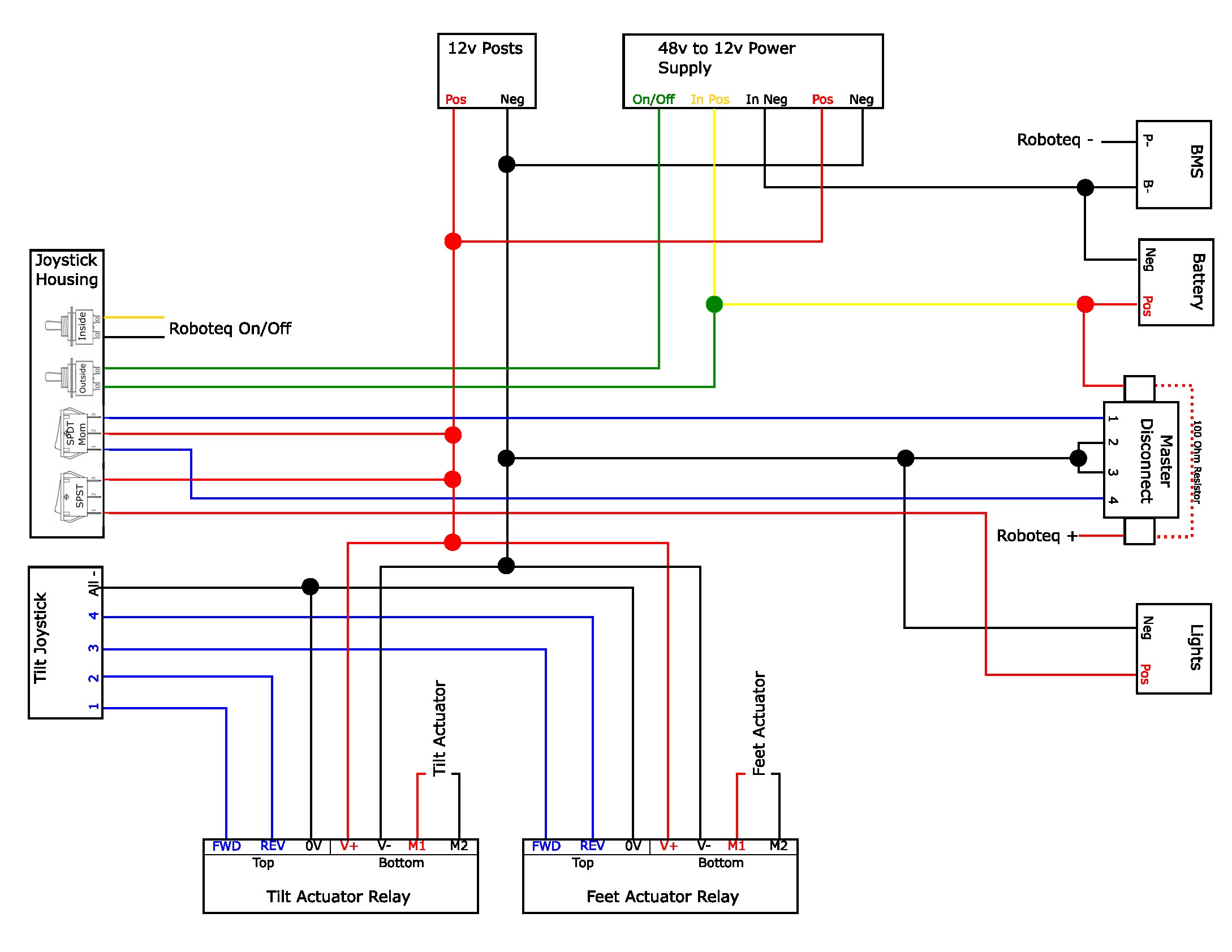
Pay special attention to how the 12v circuit is provided power and disconnected. I do not like the 48v to 12v buck converter being powered on at all times with no way to kill it. For one, it constantly draws a slight amount of power. Negligible with a large battery pack. The main reason is in case an actuator relay fails closed. You need to be able to kill the 12v system quickly to stop the actuator, especially if you are driving or under a desk and it is going up. I have never had it happen but it is possible. Note that the 12v circuit must be powered on in order to activate and deactivate the master disconnect.
The resistor across the master disconnect is recommended. It keeps the capacitors inside of the Roboteq controller charged to lessen the spark created across the master disconnect switch when it is flipped. This spark will eventually weld the contacts inside of the switch together or erode them to the point they cannot connect. I rarely flip the master disconnect either way to avoid damaging the expensive and hard to replace relay. The connection to bypass the BMS is not shown
This is not a technically correct drawing. It's something I drew simply to aid in assembly organization. It would suck to get everything together and realize I forgot one wire that requires complete disassembly to add. I'm no electromagicianal engineer. Again, this is for reference only. Don't blame me if you follow along and then get audited by the IRS.
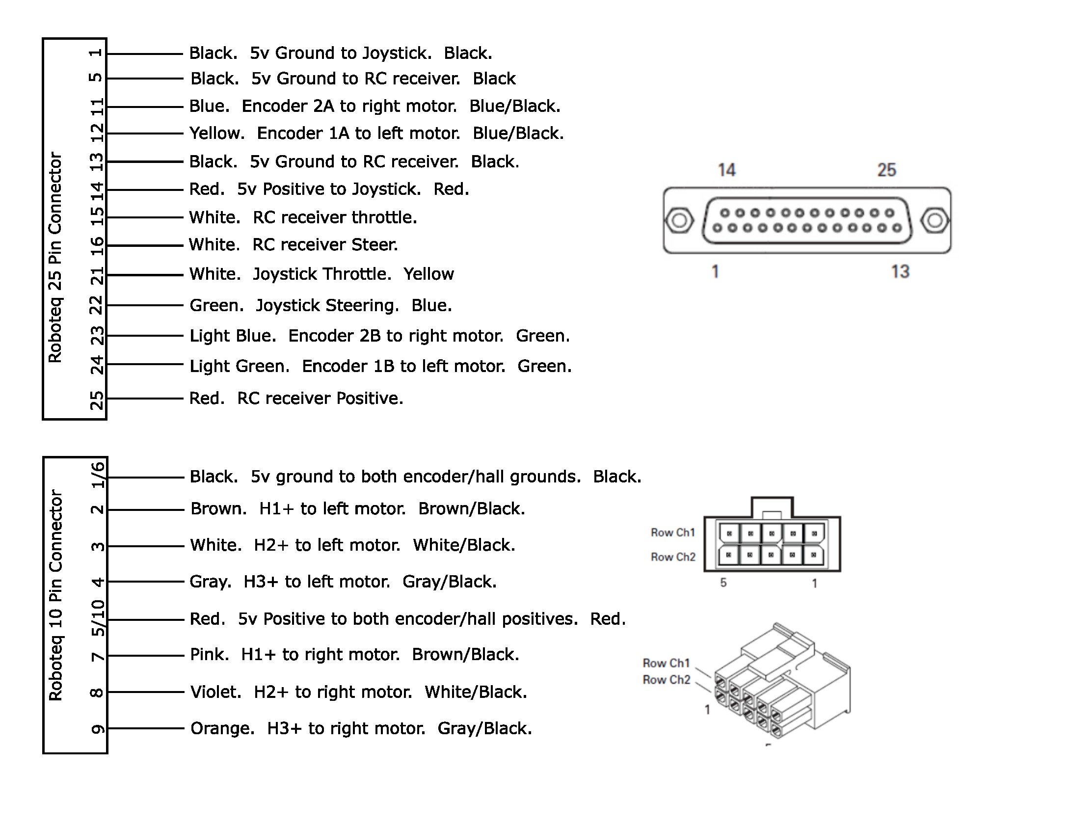
The only purpose of this is for organization and future troubleshooting. I'll know which color wire is on each end with no need for tracing through the entire looms. It also helped with building the connectors to know which terminal went to which component without looking through spec sheets while trying to solder. A little planning ahead goes a long way in saving time, frustration, and confusion later on.
Follow along to the assembly page to see it coming together.