
cad, design, and build theory
Firstly before getting started, almost everything is a tradeoff and some sort of compromise. You must clearly understand your goals and capabilities before beginning any project like this. What are you wanting to accomplish? What is your main priority? What skills and means do you have at your disposal?
Speed: Faster sounds better until you're going 16mph on what is basically a motorized recliner and hit a dog or a stump hole. Don't ask. More speed requires more stability, higher gearing, softer suspension, less darty programming/more joystick steering deadband, and more power. To get stability you need a longer wheelbase, wider track width, more caster trail, and more forward center of gravity. Higher gearing eats battery faster, creates more heat, and hurts slow speed maneuverability. More caster trail does the same. Caster trail is how far the axle centerline of the caster is behind the vertical centerline it rotates around. More trail is a bigger circle, adding stability but requiring more room. All of these characteristics are detrimental to indoor usability, long battery range, and some outdoor capability.
Outdoor Capability: You'll need lower gearing and more power for hills and towing, fat wide tires for flotation on mud and sand, more suspension travel, large diameter casters with less trail, more ground clearance, heavier duty build, wider stance, very responsive programming, and more rearward weight bias for traction and less plowing with the casters. Most of these traits hurt speed, indoor manners, and battery life.
Indoor Capability: Narrower width, shorter wheelbase, lighter weight, hard skinny tires that don't mark hard floors or pull up carpet, smaller casters with a short trail, less height, lower gearing, tilt, smoother control programming, and lighter duty build. Now you have a chair that can take you from the kitchen to the living room to eat your supper while watching The Golden Girls comfortably but can't get you down the gravel driveway to the mailbox.
Battery Range: Long battery range requires a big battery, lower gearing, higher voltage, less amps, better wiring, proper battery care, brushless motors, efficient planetary gearboxes, and low rolling resistance. Any lead based battery chemistry is completely irrelevant at this point in history. They have been for 20 years. The only suitable battery chemistry currently available is lithium based LiFePO4. Properties of lithium increase the cost, complexity, and difficulty of the design. More details on the battery page.
Planetary Gearboxes: While more efficient, last basically forever when used within tolerance, require no maintenance, and typically stronger than comparably sized gear reduction types such as worm gear or chains, they have their own caveats. For one, they are more expensive. Second, they are usually available in less gear reduction steps and each housing size will go in large even steps from 10:1 up to 15:1 then 20:1 and get physically longer as more stages are added to increase reduction. You're out of luck if you really need 12:1. Third, unlike worm gearboxes, they can be turned backwards, which means they are not an automatic parking brake. External brakes are required if you need the chair to lock when powered off. The motors will require quite a bit of force to turn due to the generator effect when powered on though. I do not use brakes. It is very hard to push when powered on. It will slowly roll on a steep enough hill. Lastly is the noise. Even expensive units with helical cut gears will whine.
Increasing Voltage: This is one of the few instances where there are almost no tradeoffs. Almost. Increasing voltage raises efficiency for the same amount of power output. Total power is measured in watts. Volts x amps = watts. Amps are what create heat. A 24v system would need to push 125 amps through the motor to get 3,000 watts of power. A 48v system would only need to push 62.5 amps through the same motor to get the same amount of power. However, the motor would spin twice as fast. Now increase the gear reduction to get the same final drive speed. You have just increased your torque by a factor of 4 with the same amount of power, all while generating less wasted energy as heat! Smaller wires can be used as long as the insulation and connections are good enough.
Note that I said almost no tradeoffs. Higher voltage requires motors designed to take the increased voltage and RPM, supporting components that can handle the increased voltage, room for a battery that can output 48v and supporting charging system, a voltage reducer for things like lights and actuators designed for lower voltages, and a controller designed for the increased voltage with enough headroom that regen spikes while decelerating or pushing the chair won't cook it. Unfortunately, there are none available that will work suitably out of the box. More on it down below the CAD stuff. Upping to 96 volts would be even better, but with DC, you're getting into the realm of dangerous and designing everything from scratch. Something I would do one day if time and money are no object.
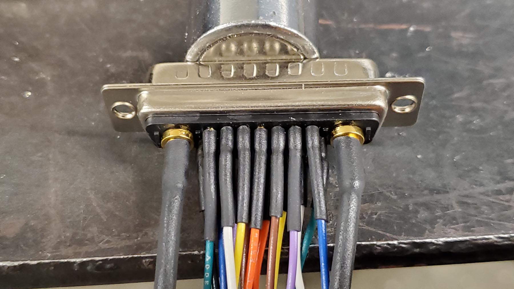
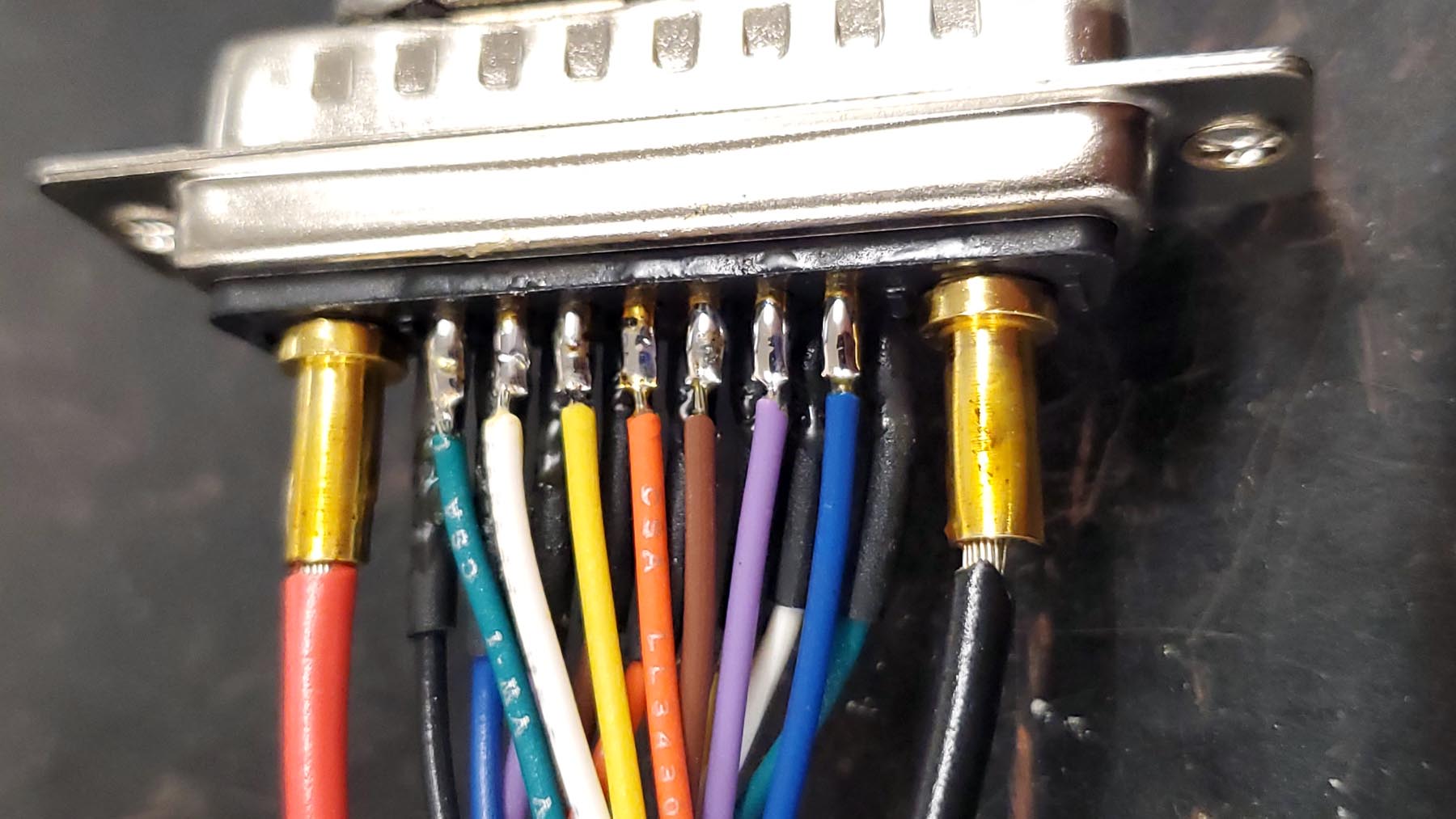
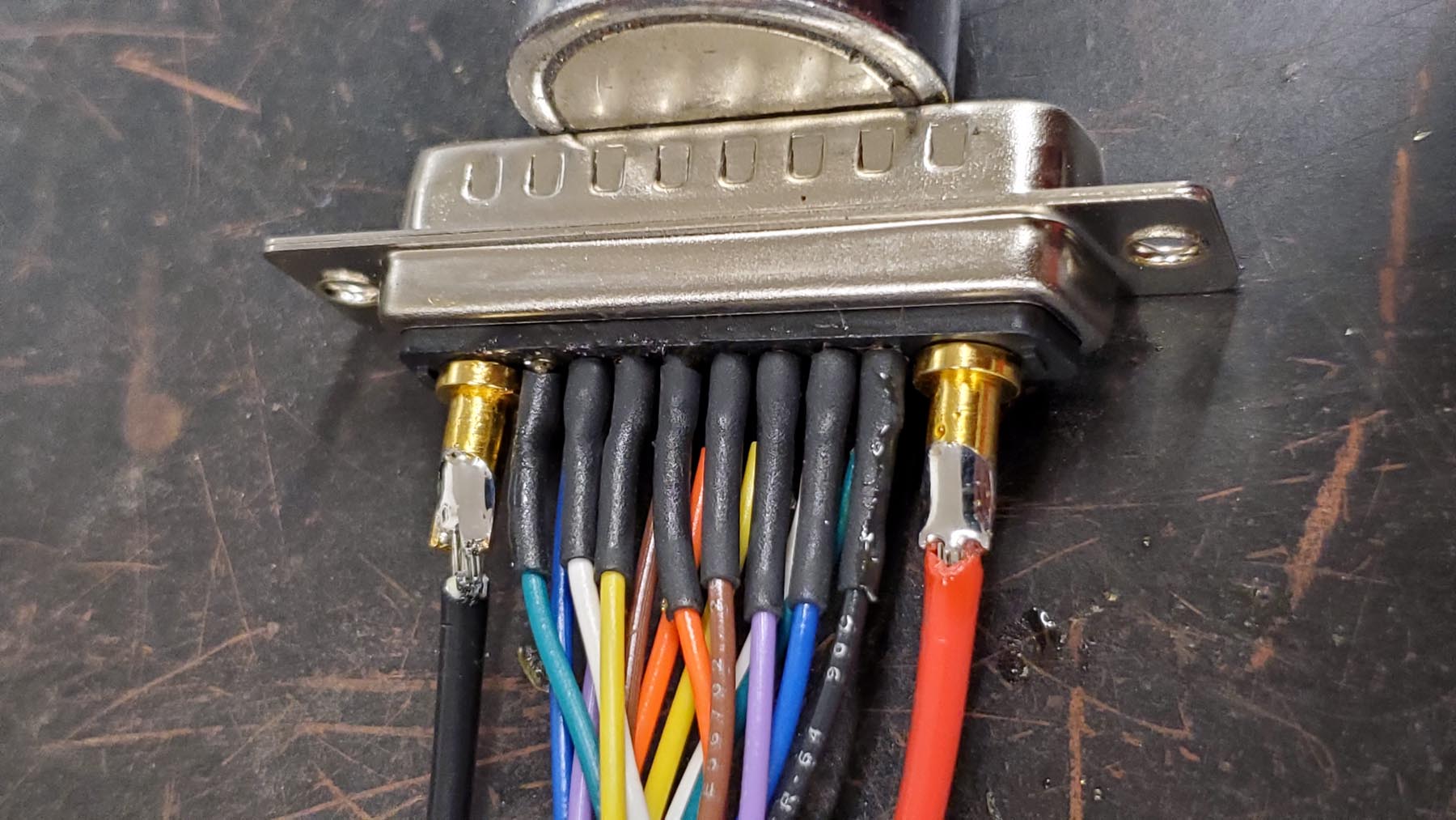
Brushless Motors: They add a whole new level of complication. 12 wires are required with brushless vs just two with brushed motors. You have three heavy UVW wires for power, three signal wires for your hall ABC sensors, a 5v supply and ground for your hall wires, two encoder signal wires for your encoder A and B sensors, and a 5v supply and ground for your encoders. These all need to be twisted or at least shielded to provide a clean signal. They must also be durable. The motors will not turn if even one is broken. The wiring is not the only issue. Finding suitably spec'd brushless motors or having them built is difficult and expensive if you can find a vendor willing. Add to that, if you do find a vendor willing, especially from China, will they actually be to your specs or will they just lie to sell you something? It requires accurate and expensive equipment, along with the knowledge to use them, to test for yourself and see.
The basic way brushless motors work puts them at a big disadvantage. They have very little starting torque. They are amazing once they start to move, but that initial rotor movement can be impossible to achieve, at least not smoothly, without a few critical specifications being met in the motor windings, sensors, and controller configuration. They need to be a correct impedance, high pole pair count, high quality build with accurate hall sensor placement, same for the encoder with counts and output the controller can read, and the exact matching controller configuration for smooth sinusoidal commutation to occur. I suggest avoiding trapezoidal commutation. It is easier and more forgiving but louder and not as smooth at low and mid RPMs. The motors alone would require a whole page to discuss.
Now that the limitations of each goal are established, it's time to design around the compromises. Three separate chairs would be ideal: One for indoor and travel, one for outdoor fun, and one for outdoor work. This is not feasible if you're stuck in whatever you start the day in, which is typically the case for people in this market segment.
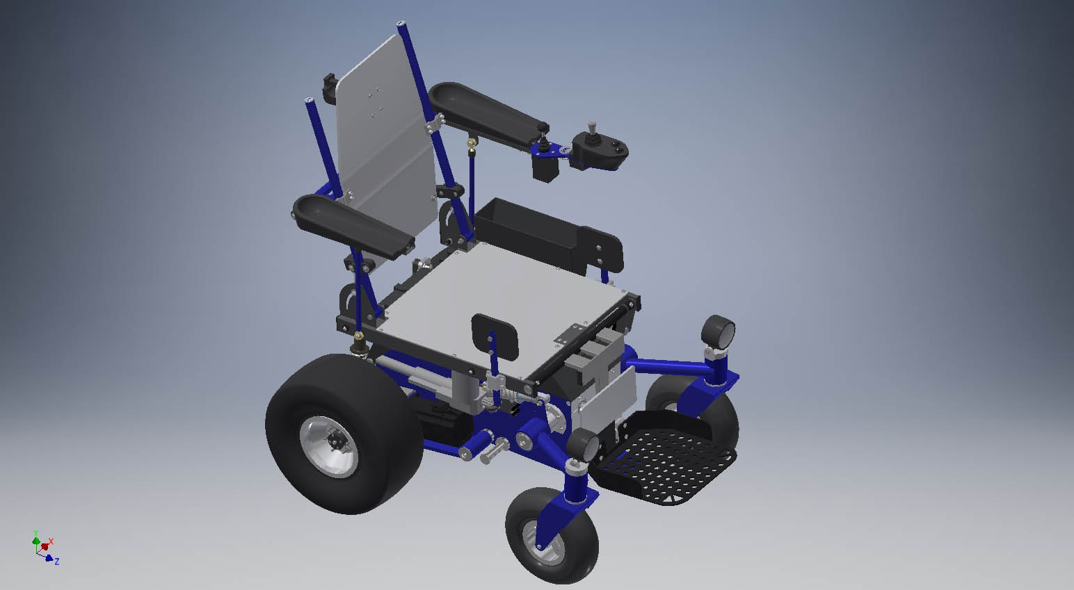
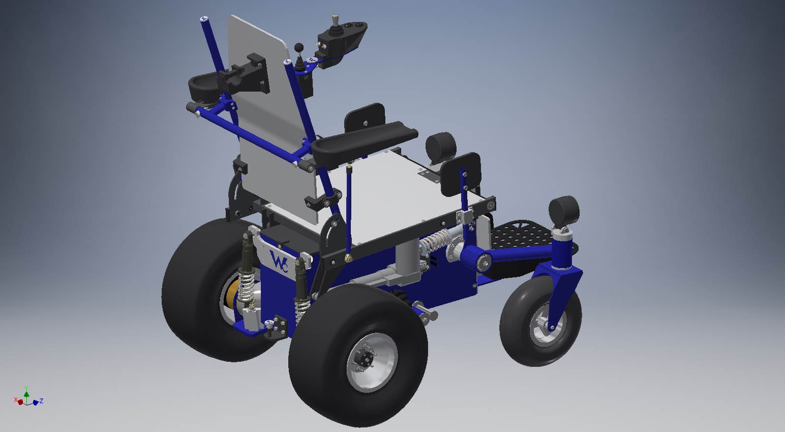
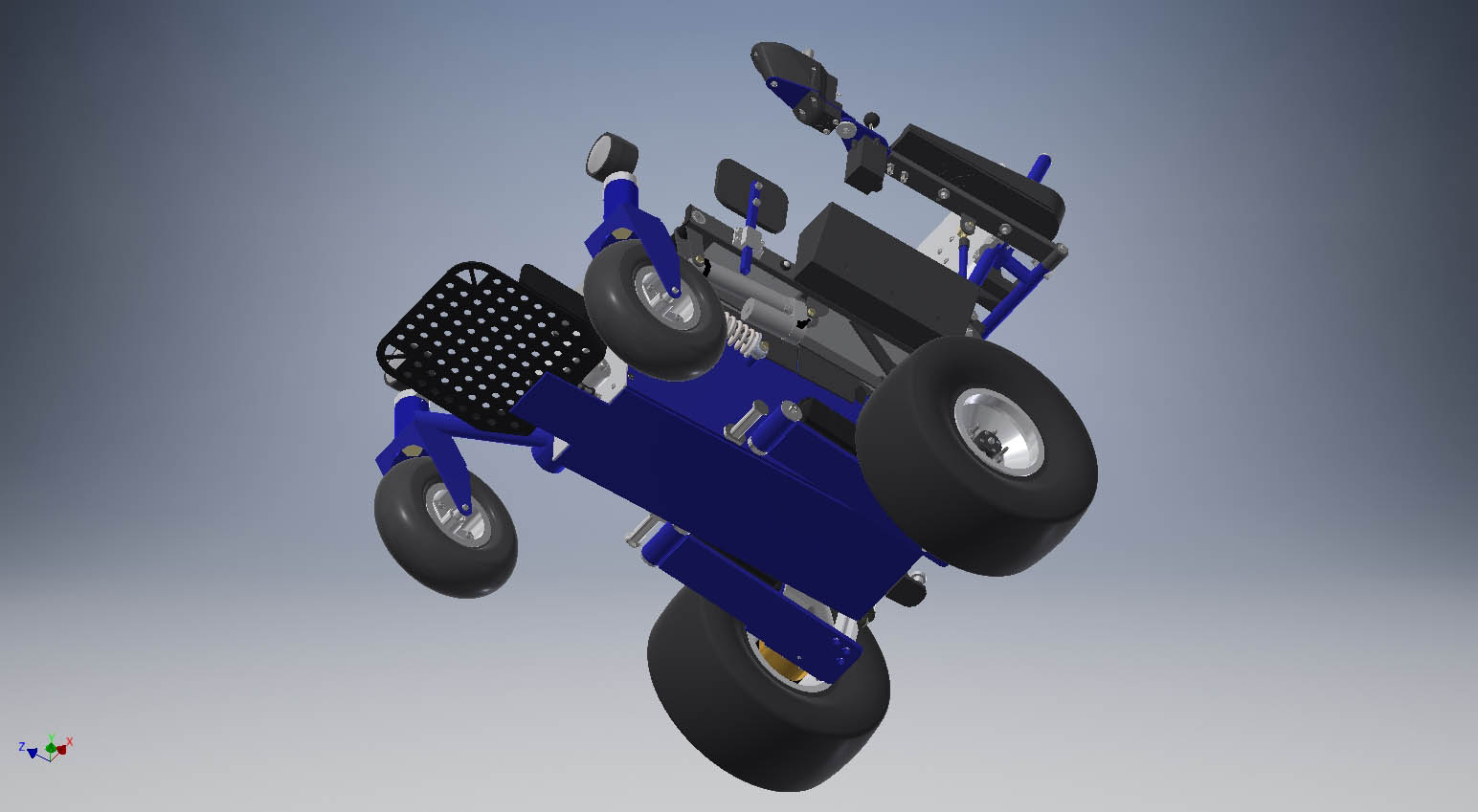
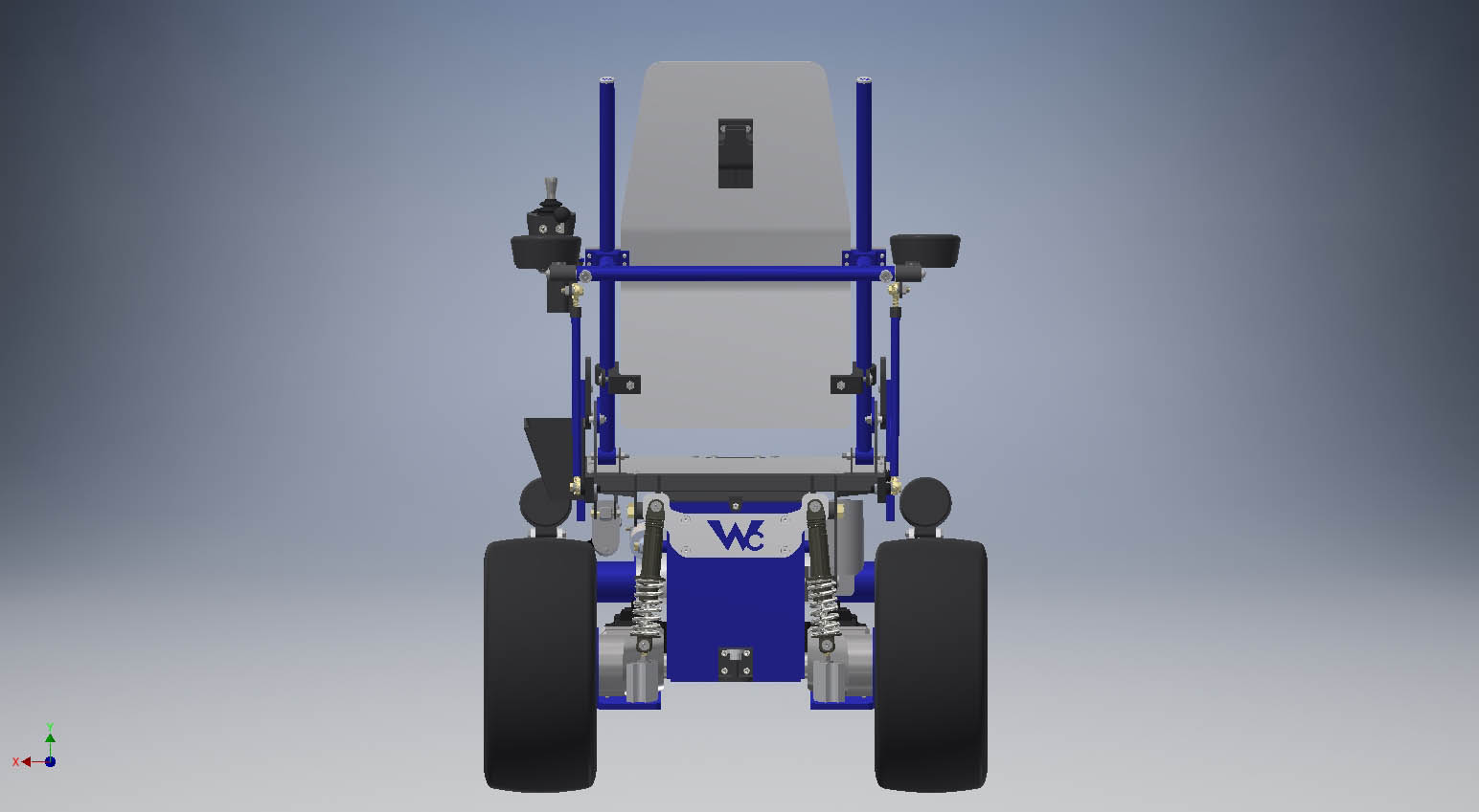
Designing around all of the constraints needed made finding off-the-shelf parts difficult. The chair must also fit in my truck so I can drive along with placement for the docking mechanism. Things like ground clearance must be estimated due to tire pressure and suspension settings.
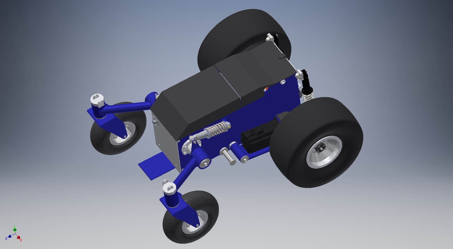
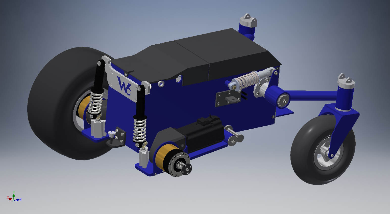
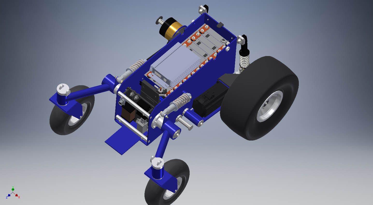
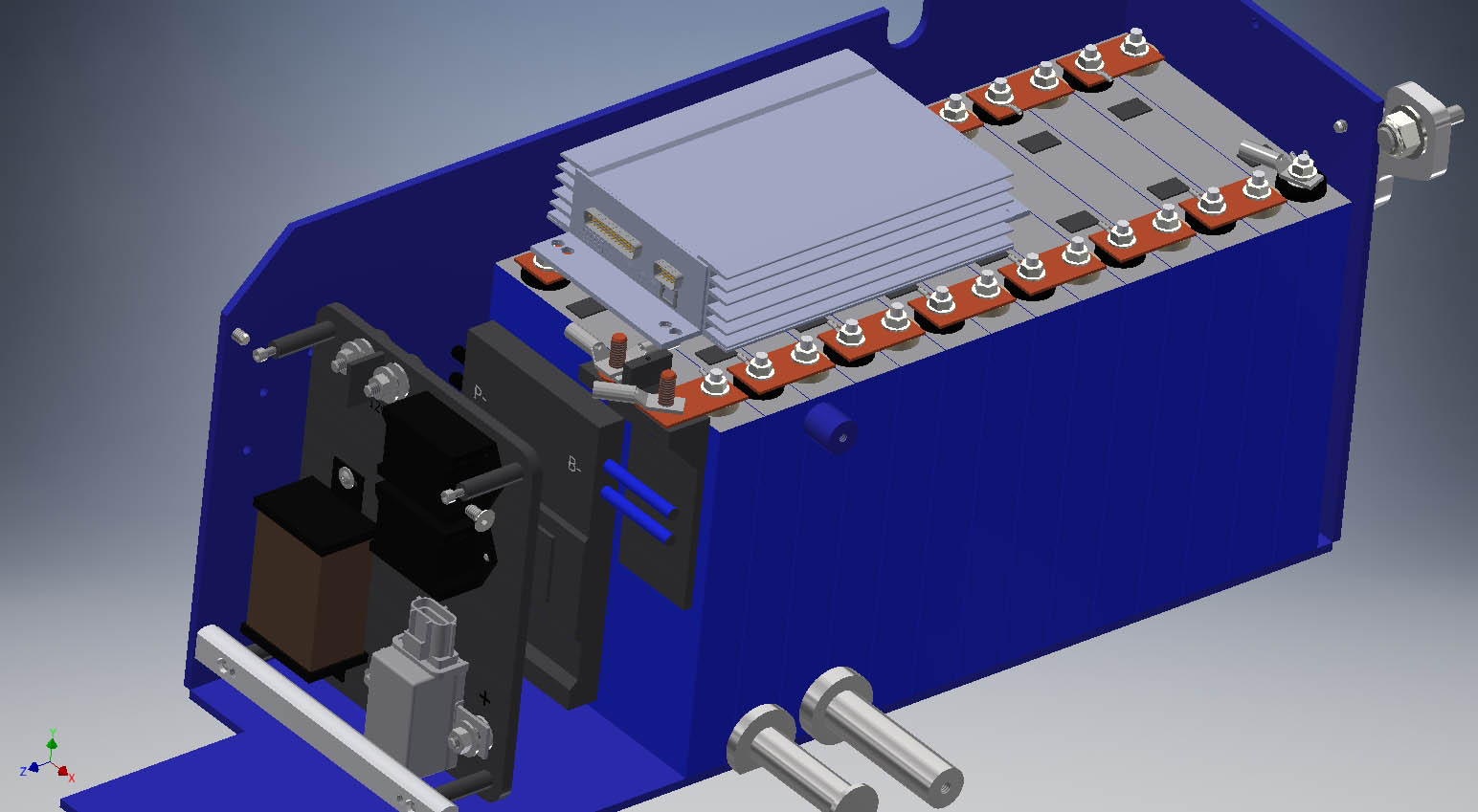
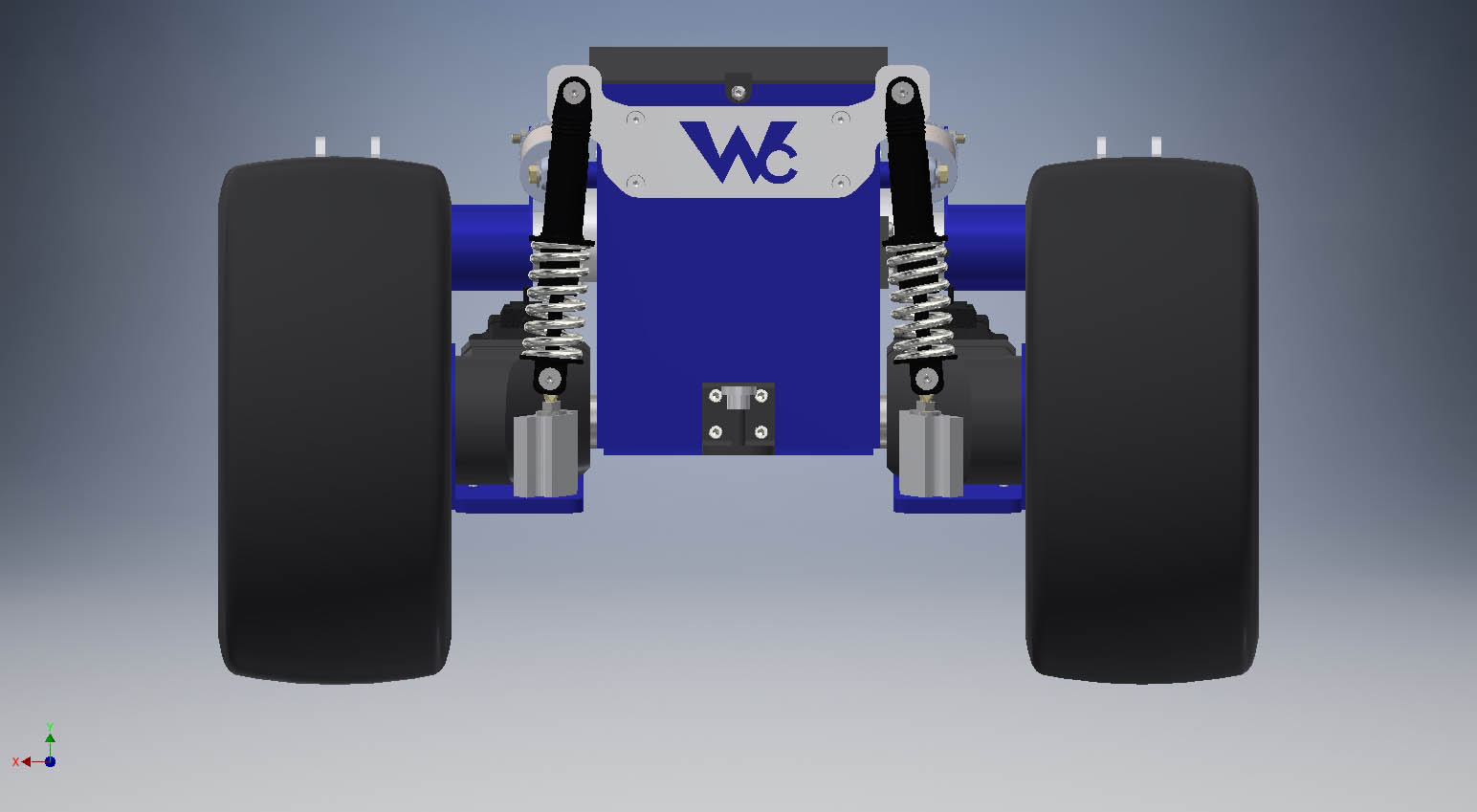
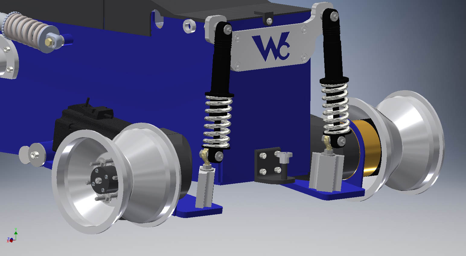
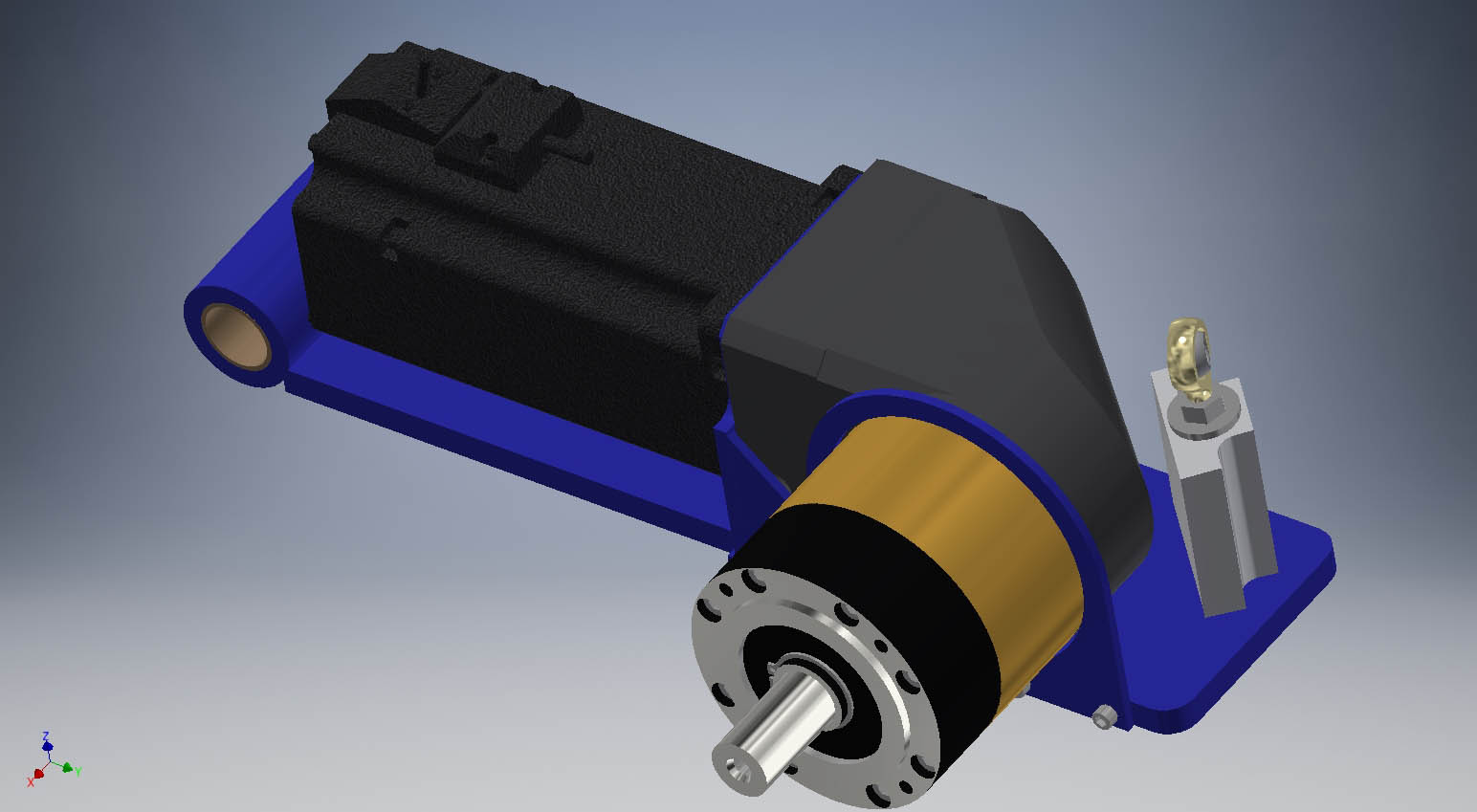
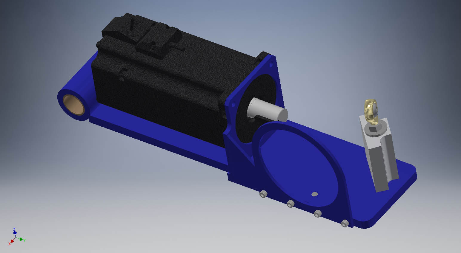
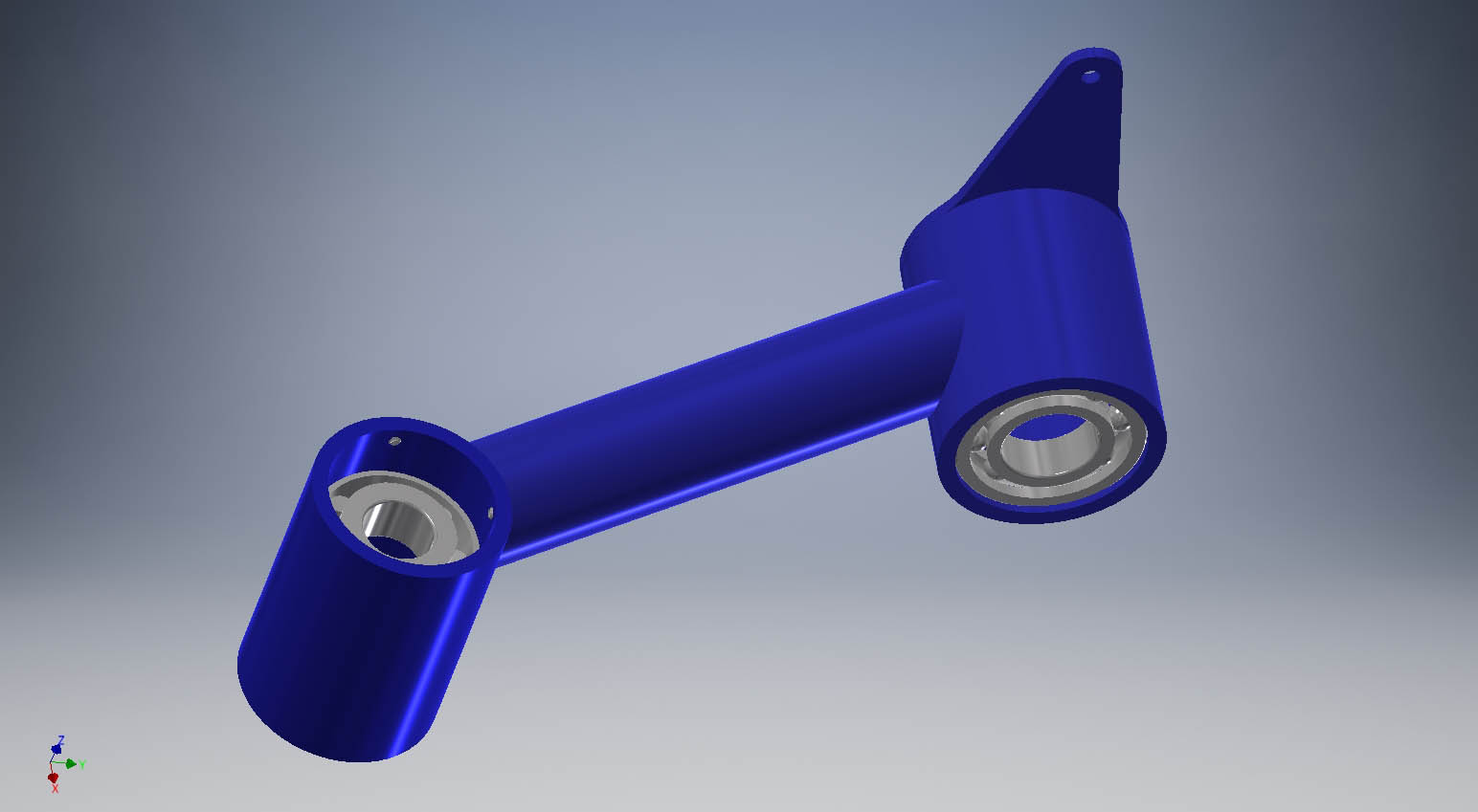
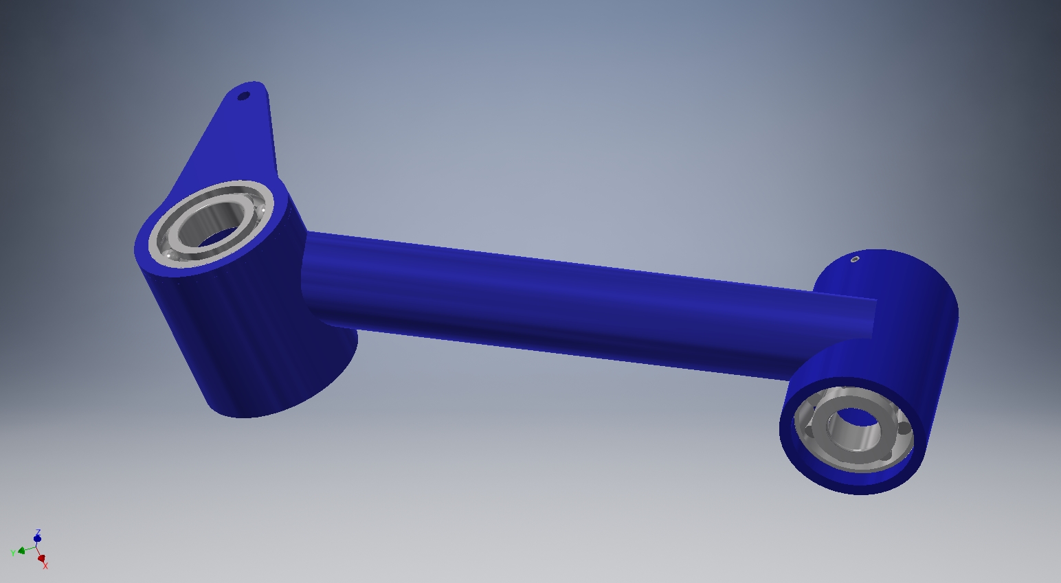
Most manufacturers of things like motors and gearboxes will typically provide you with a solid CAD file if you ask. Open source IGES or STEP files are preferred. They will rarely provide native CAD files from the design software such as Solidworks or Inventor. Always double check them once you have the part in your hand for discrepancies before proceeding with cutting metal. On the third chair I built I had to completely redesign and rebuild the blue parts you see below and shock mounts (not exactly like these but similar) because I made the parts based off of their supplied drawing while waiting on the custom wound motors to arrive. The motors were 1/2" longer than the drawing. They would not fit.
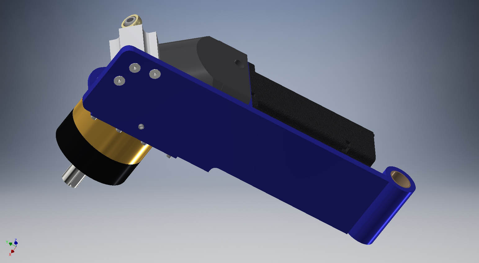
The basic electronic components were purchased then measured and modeled before building. This chair has a more robust and simpler electronics system than on previous designs I built. Live and learn.
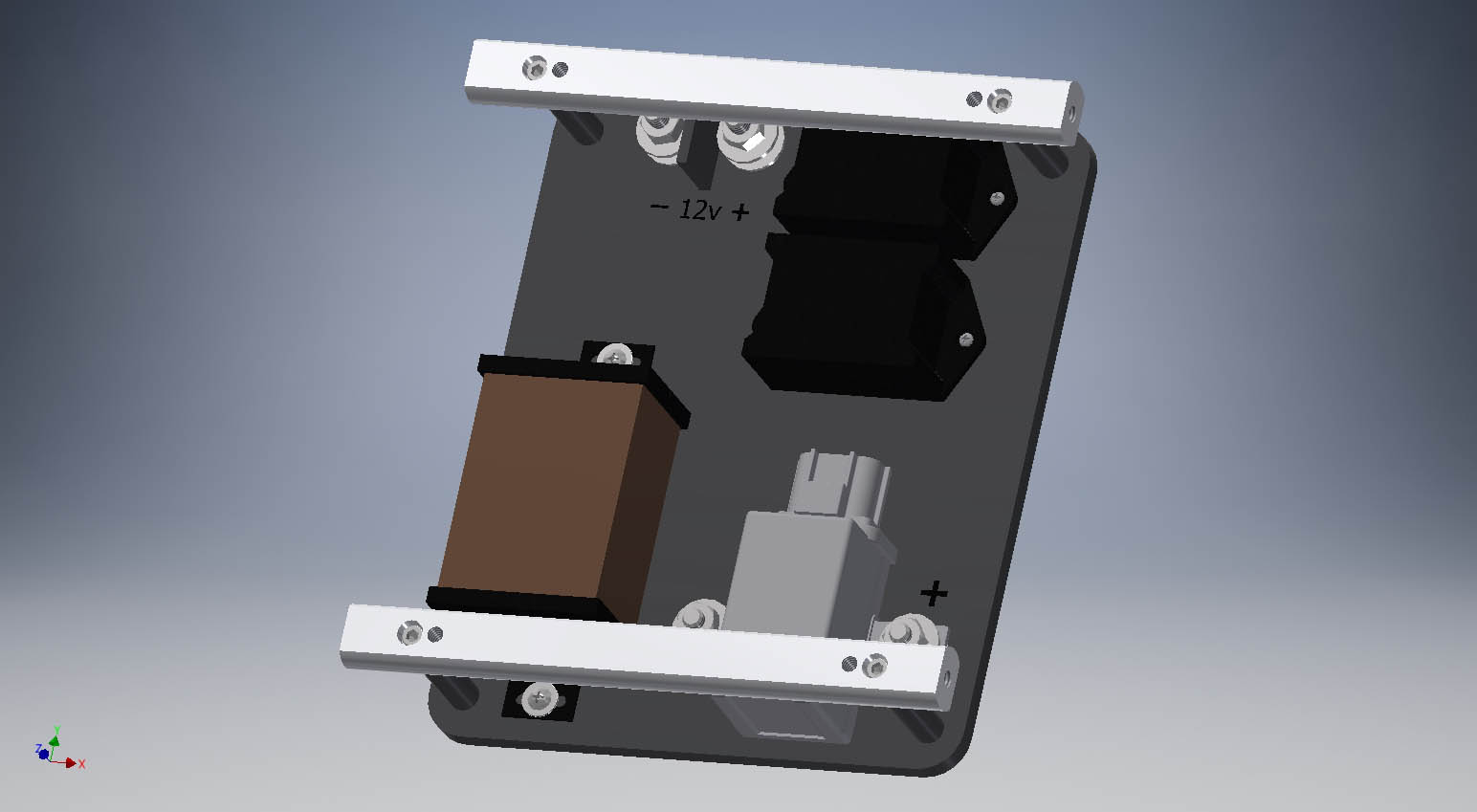
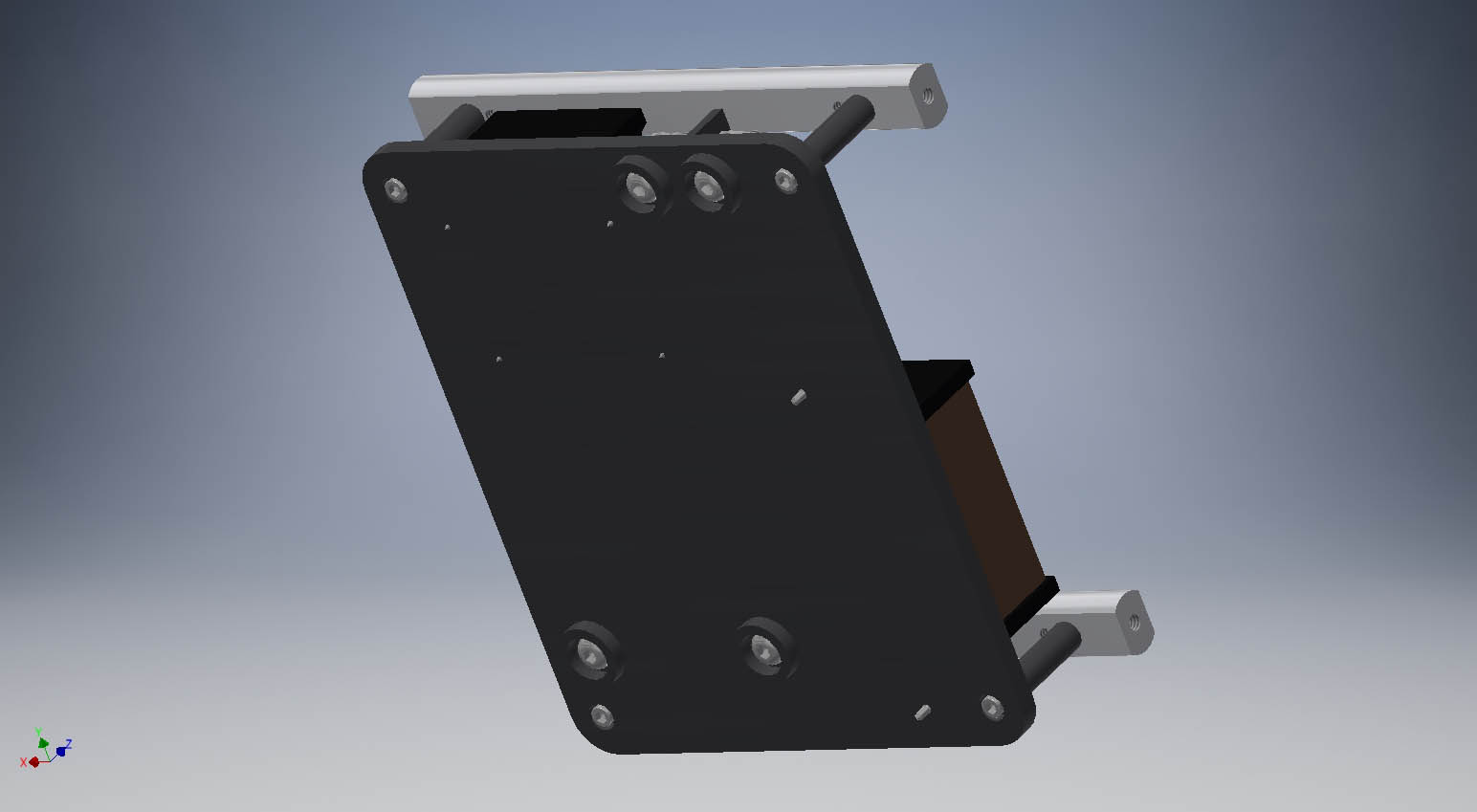
The charging connector appears to be floating in space. It is not. It is installed in the front cover. The visibility for it is turned off. This lets you see how much room you have that would be hidden otherwise.
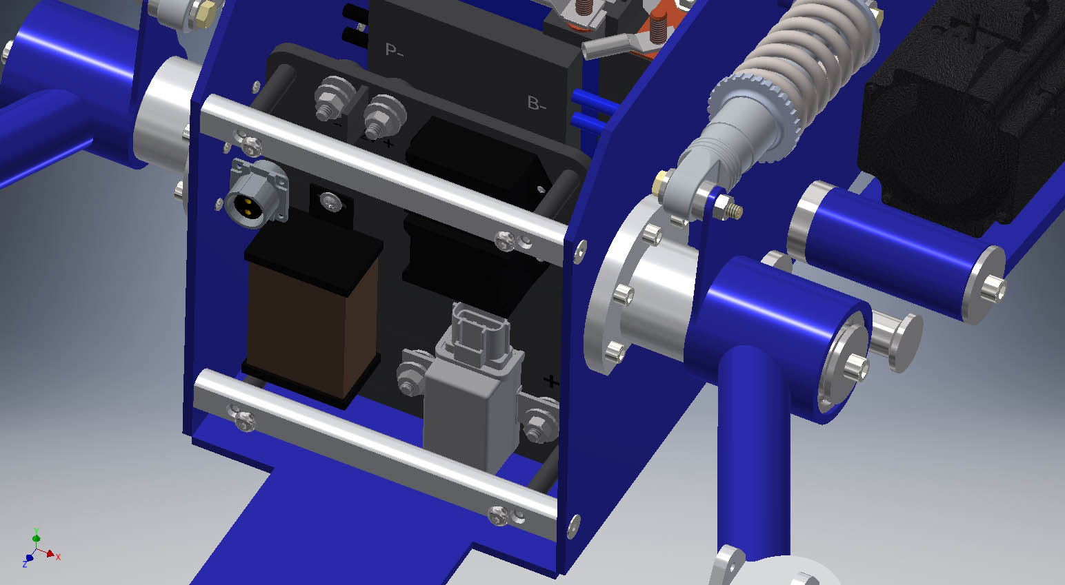
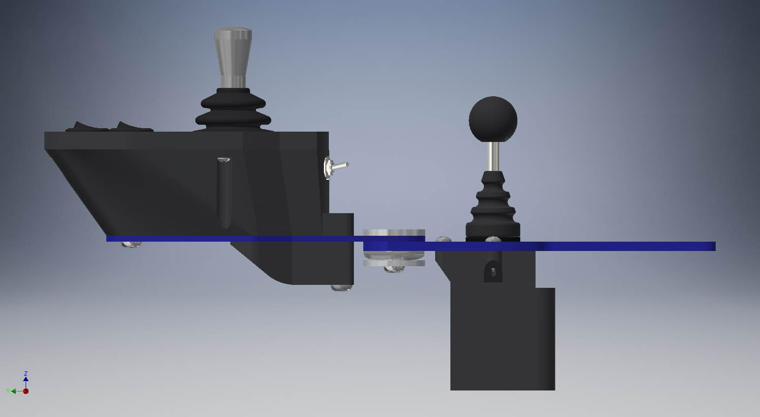
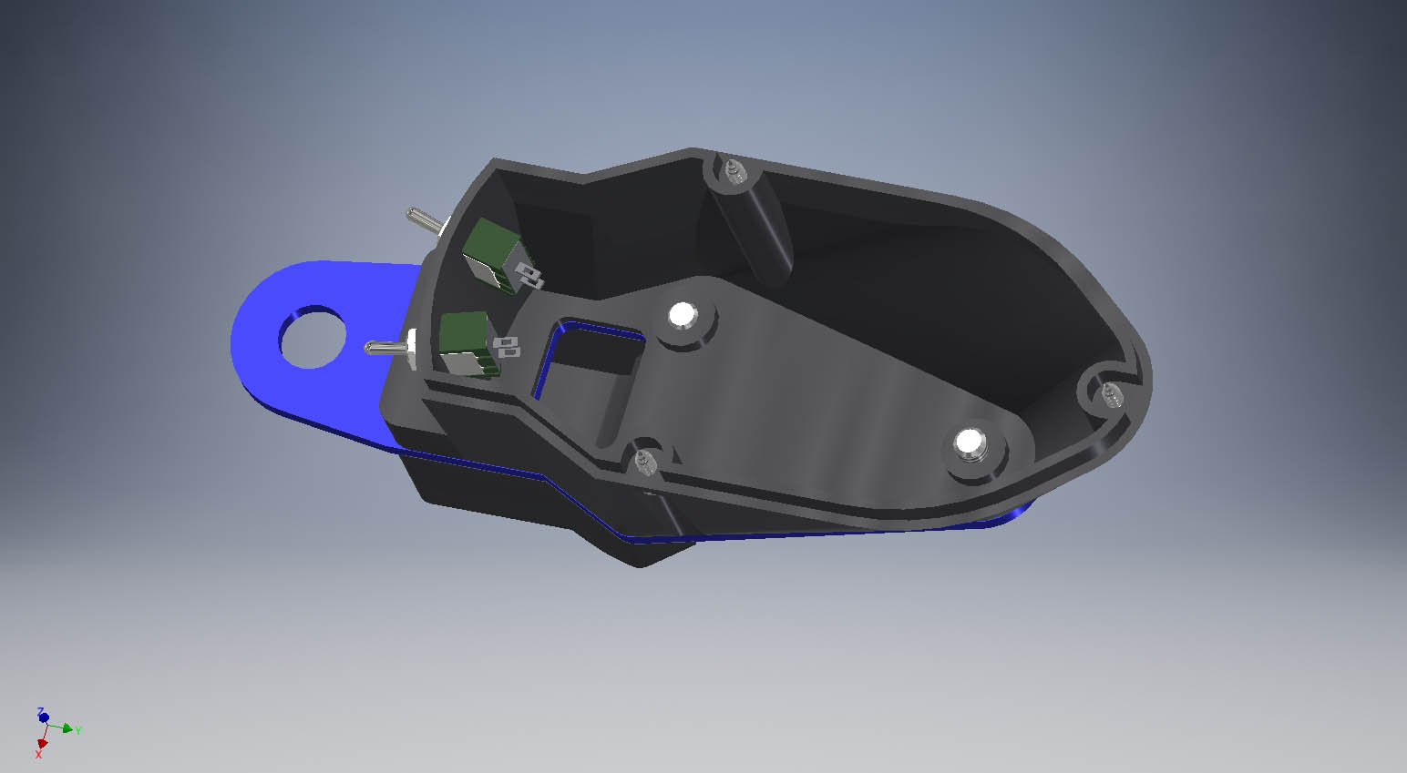
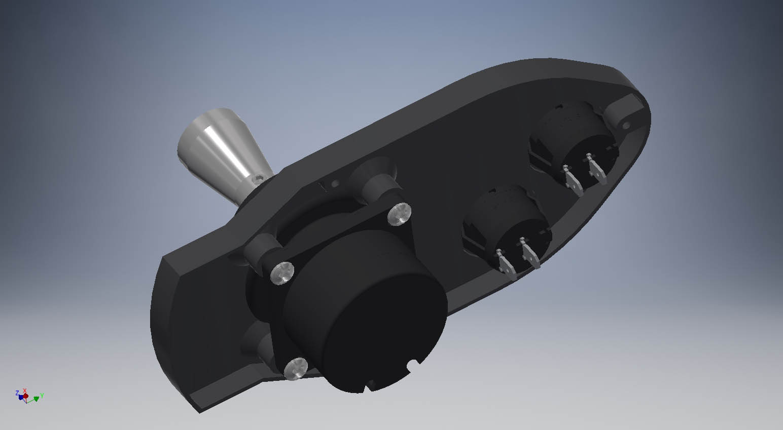
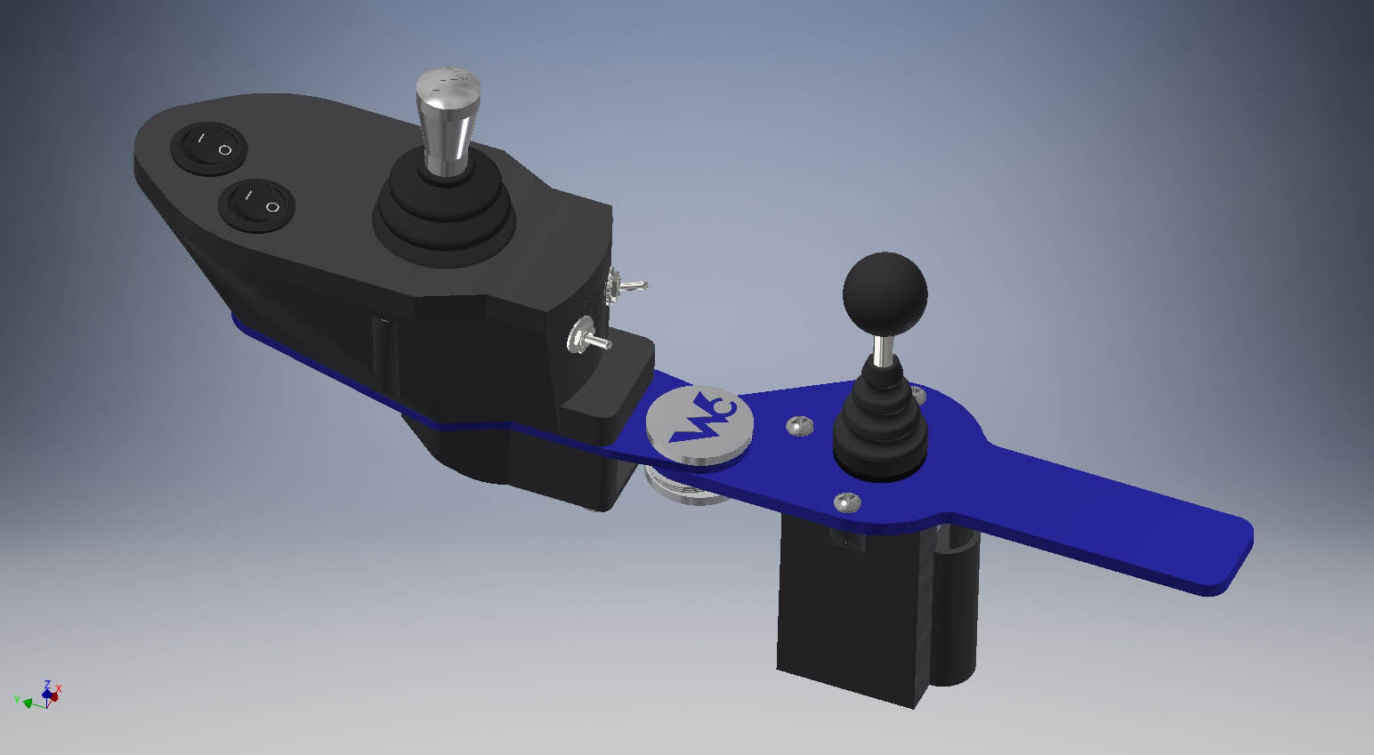
The joystick housing looks empty without the mess of wires that are required in real life. One thing that does not match what was actually used is the front rocker switch. The real chair uses a single pole double throw momentary switch for the master/emergency kill switch. The two in the model are both single pole single throw latched rocker switches. The dimensions are identical though.
The seat design is a bit complicated and a little bit of a pain to build due to all of the supports. I have built several of these though and this design has proven reliable and strong.
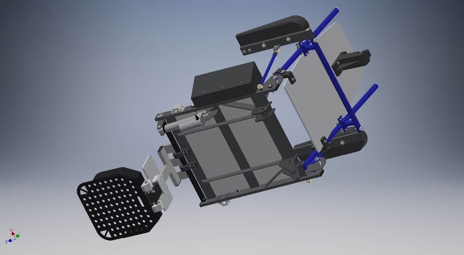
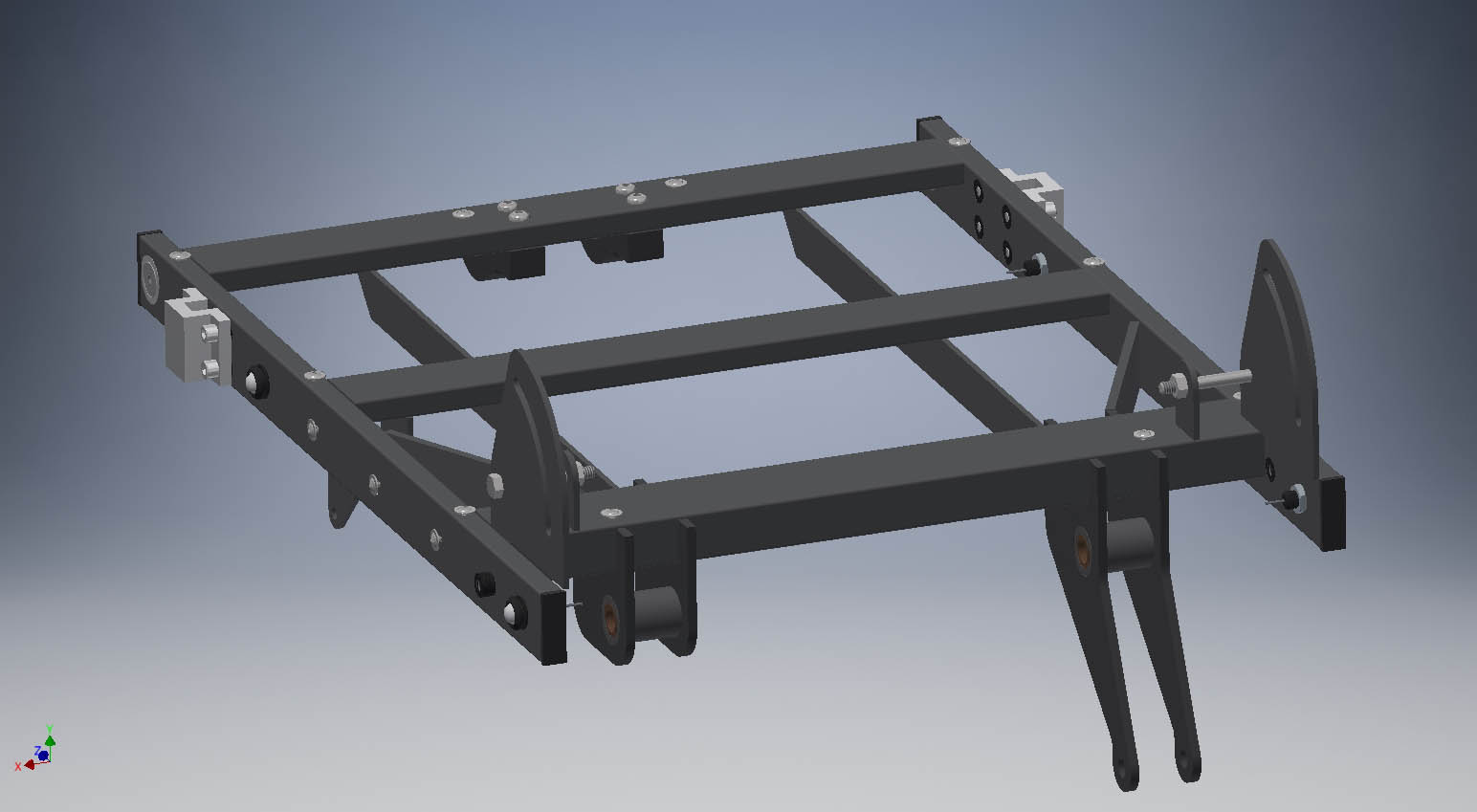
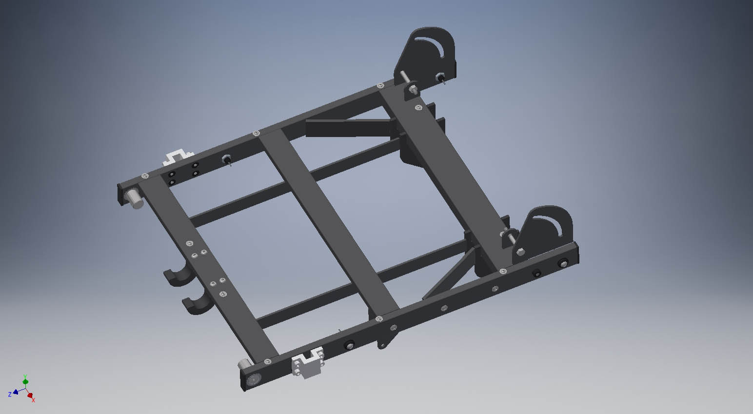
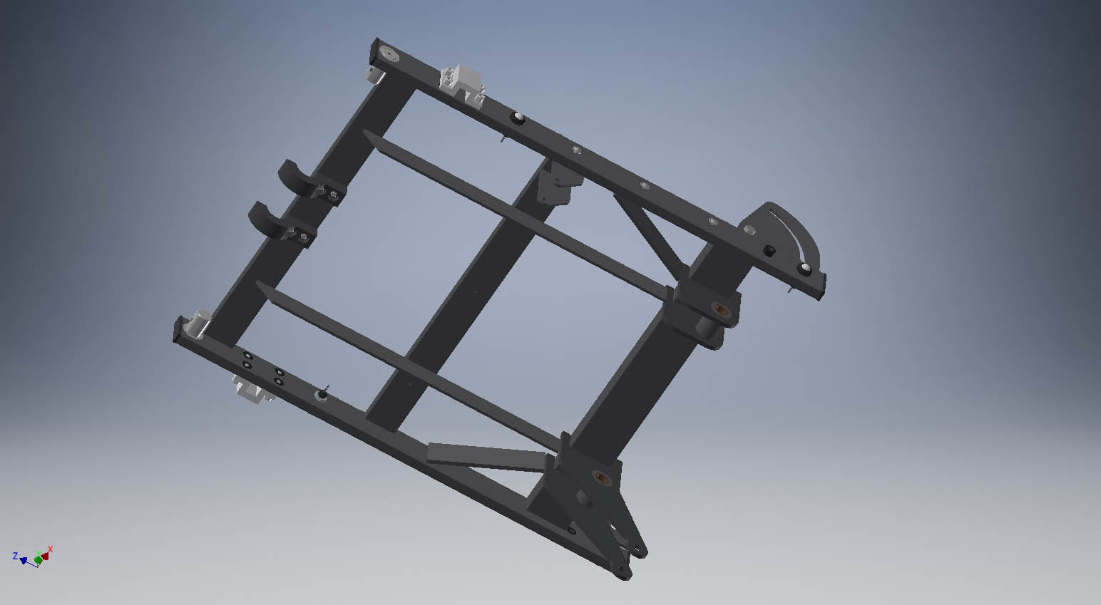
It would have been much more difficult to get the angle and relationship of the swingarm mounts and caster barrels correct without CAD first. It still took a bit of guesstimating to assure the caster barrels were straight up because it can vary with tire pressure and suspension sag settings.
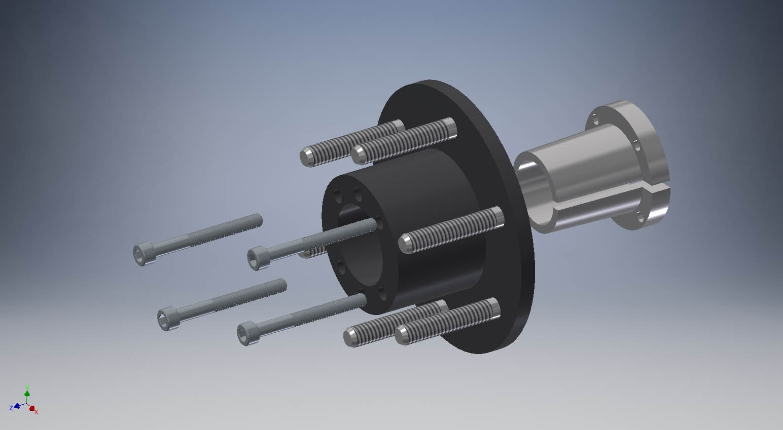
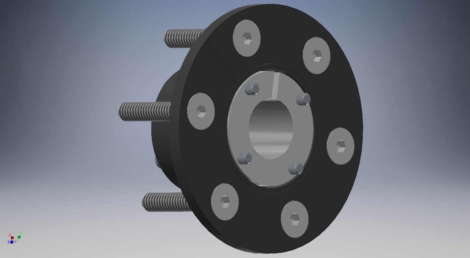
This is how the taperlock hubs go together
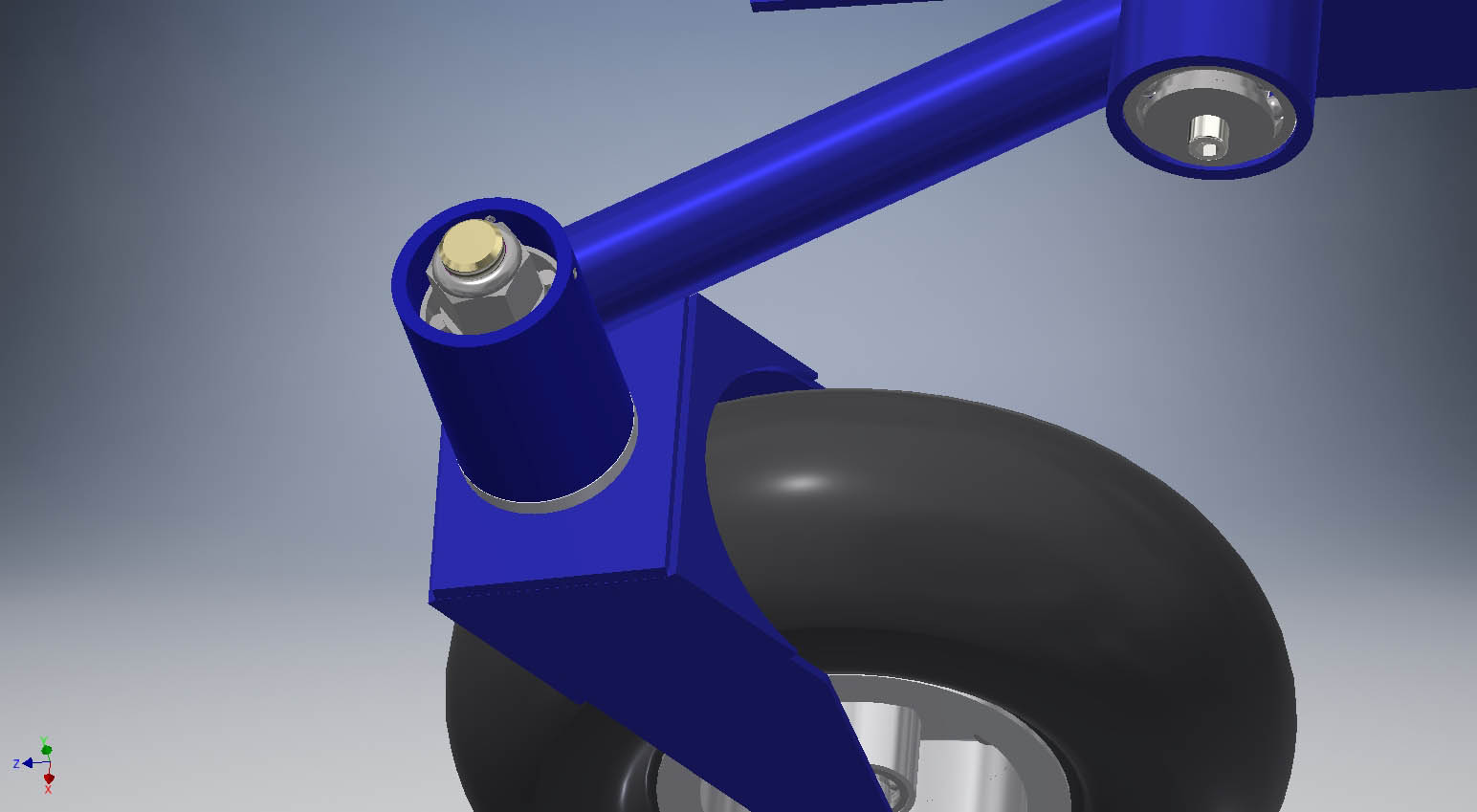
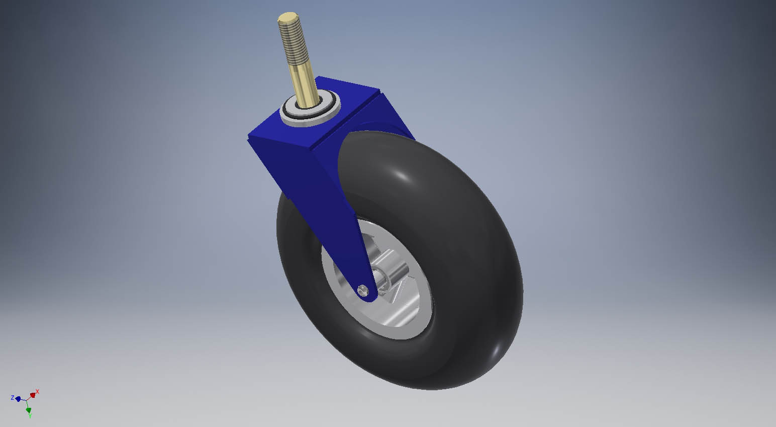
The caster forks use a pair of 3/4" id tapered roller bearings like in a truck axle. They take a beating. Standard roller bearings do not last. These also have a slight amount of preload applied to help reduce caster shake at speed. The bottom has an O ring seal to help keep water out
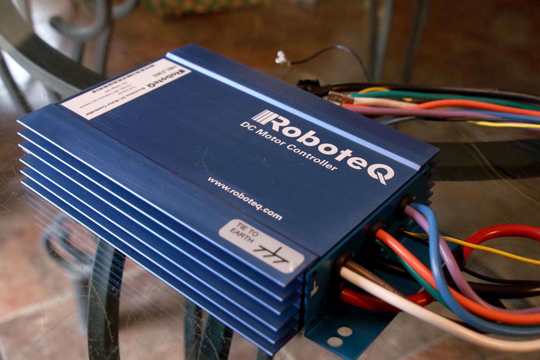
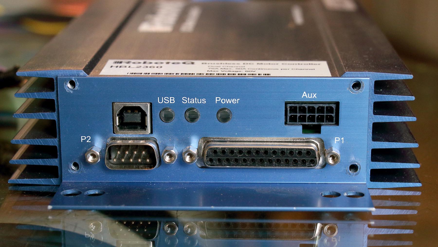
Controller: This is a bucket of worms that would take multiple pages to cover. I'll hit the fundamentals only.
Follow along to the hardware build page to see these parts coming to life.