Hardware Build
Nothing here is an off-the-shelf wheelchair part. Everything was designed and made for a specific purpose. There were a few design characteristics limited due to the equipment I have to build with along with physical limitations.


After op 1 and op 2 on the CNC machine they go back in the manual lathe to have the hole for the swingarm axle bored. This could be done on the CNC as well, but the tools are long and it takes a while to setup and program for each tool. I'm limited on Z height in my CNC and do not want to shorten the reamer just for four parts. If I was making 50+ then it would make sense to sacrifice an expensive reamer or purchase a dedicated one for the sake of time. Also, reamers are finicky to get the correct dimension they're designed to cut within an acceptable tolerance and surface finish. They are picky about the prehole size, the lead in chamfer, runout, and speed they are ran. A few test parts would need to be ran and possibly scrapped first. When manually using one, you can feel when they are cutting correctly and happy. Using a boring bar to finish is even more accurate. Not with my hands trying to measure an id though. Lastly, they go back in the CNC for the countersunk bolt holes that retain the swingarm axle.


Video below machining of the swingarm mounts.


Here are a few videos of machining these. And yes, there are different stock sizes. I ended up making a few sets for my older chairs and used scrap..

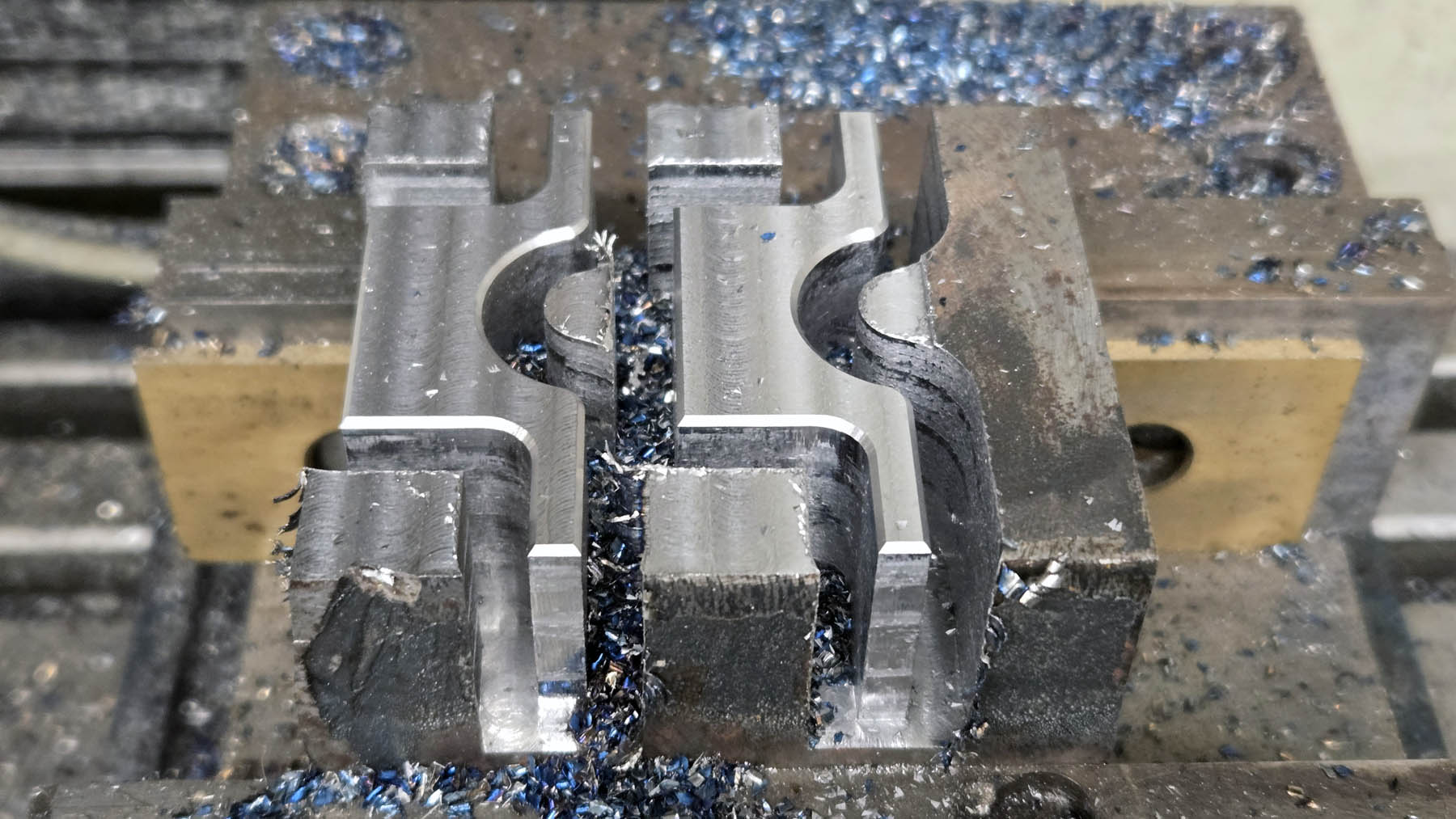
Swingarm axles. Everything doesn't always go correctly. I originally made these from 304 stainless since I had a stick in stock. Unnecessary but could make them easier to remove in the future since there would be little corrosion.

This is why machined parts from martensitic stainless steels are more expensive. It can be hard on tooling. This tap was not designed for stainless. It would have not broken had I taken 10 minutes to set up the proper tool and used the proper lubricant instead of worrying about recording.

4140 would have been the best choice but overkill. These are 1 inch diameter x 4.375 inches long and supported by two 1x2x1/2 inch ball bearings. If I manage to bend them, then I have bigger problems to worry about.

These are the docking pins for the lockdown mechanism in my vehicles (more on that device will be on another page) and the axles for the rear suspension. Both made from 1018 steel. Both are simple straightforward manual turning in a lathe. The suspension axles did have a tight tolerance of .001 inch to hit on the diameter.


Small parts like this don't look like much but are time consuming. Each one requires multiple tool changes. These are some of the armrest and other small hardware parts. Step 1 is load up my "tool cart" with what I need...


These also don't look like much but were tedious with the tight tolerances. This is all hardware for the shocks. They're from 1144 steel. Quite strong and machines beautifully. It is a great material choice when strength over price is what you need as long as you don't have to weld it. The factory paper thin hardened steel race over an aluminum bushing sucks for this application. They're not really designed for this type of use and load directions. The last chair I built had gotten sloppy. Pulled it apart and I had worn them out all the way through the bushings and the hardened steel race. You could almost take the shocks off without removing the bolts! After doing it this way it is still squeaky tight after several years.

Power die threading the UNF 1/2-20 side of the upper rear shock mounts. Quicker and safer than single point turning and easy to tune the thread depth by tightening/loosening one screw on the die holder I made this die holder.
Original on the left. Redesigned on the right. The original aluminum bushing rotates on whatever shaft you put it on. In my case it was grade 8 bolts. Add a little dirt or corrosion and it doesn't take long to wear out. The design I made uses an Oilite type bushing that is pressed into the housing.

I also made some aluminum washers to help keep out the nastiness


This is how the heel plate that goes on the back of the footrest was made. You don't need artistic ability or steady hands when you use the correct order of operations.
Front Cover Mounts. The Electronics Board also mounts to the back side of these with four standoffs. They're inside the battery box and held on by two countersunk bolts that come in from both sides. Not complicated to make nor require great precision. Just a bit time consuming because so many steps and different setups required in both the lathe and mill.


Not absolutely necessary but gives a finished appearance, helps stop scratching arms on the end of the uprights, and prevents kids and coworkers from dropping things into the hollow upright tubes.

Little things like this go a long way into adding to the total polished feel of the finished product. Flat or countersunk bolts don't really like to be tightened against a rounded surface. These bolts go through DOM round tube to hold the two Armrest Mounts in. These countersunk washers give the tapered head something to tighten properly against as well as look good.


Joystick Swivel Mount. This allows the joystick to swing about 200 degrees left and right. Three belleville washers (springs) go under the cap.


Rear Shock Mounts. Straightforward simple machining except for the top face with one bolt hole. That face is on a 4 degree angle to align the rod end straighter. That keeps the rod end that the shock mounts to in the middle of its range of motion. Without that angle the bolt going through it could bottom out at the ends of the suspension travel.

Custom UNF 5/16-24 flange nuts whittled out of 4140. Not really necessary. Any flange nut would have worked. I had this piece of scrap and wanted the base a little larger than a standard flange nut. One is dark colored because I didn't realize the parting blade was dull until committed. It got hot. No harm..


Upper Shock Mount for the rear shocks. Cut from a solid piece of aluminum plate. The tabs are left so the vise has something to hold onto.

It can be tricky programming the tabs to be the correct size. They must be small enough to be broken off once finished but strong enough to hold the part in place without collapsing under the pressure of the vise as the part is machined.

These clamp onto the uprights. They are what hold the armrest mounts on. The 7/8" DOM tube presses into the recesses then is welded. PROPER welds alone would be strong enough, at least on paper. The recesses and press fit are more so for locating accurately. Cut from 1018 flat bar stock.


Flip and machine the excess off. A little wasteful but I already had excess 1018 flat bar in stock for another project. Also, quite often it is more economical to pay a little extra for slightly oversized material so you have something to hold onto instead of more complicated workholding strategies, especially if you are only making a small quantity.
If I was making 100 or more of these it would be more economical to use $40 of material to make custom shaped vise jaws to hold onto the parts in secondary operations to save money by using smaller material for the parts, much faster setup times, quicker machining, and less tool wear.

Quick phone videos showing how they were machined along with the straps for them.
The rear wheel halves have a spacer with an O ring. They can be finicky to seal and makes removing the wheel and tire tricky. Nothing holds the spacer in place when the bolts/studs are not in it. It makes for a long day if you let that spacer fall down inside the tire. It's difficult to get the tubeless tire off. I've also had a few of them leak. To remedy this and ease assembly I faced all of the wheel mating faces perfectly flat and added an O ring groove. You can tell how not flat they were by the pattern left after the first pass. I only had to remover about .015" to get them truly flat. Probably unnecessary and within the sealing tolerances of the O rings but no reason not to.


Caster Barrels and Swingarm Bases. Straightforward lathe turned parts. Fairly tight tolerances on the id for the bearings to press fit into. The lines on the outside are not mistakes. Those are .0015" deep locating grooves for the swingarms. See below how they worked. Much quicker and more accurate to mark it on the lathe using the digital readout than trying to fit it up measuring with calipers or similar.

Front Swingarms. There are tools made specifically to cope pipe. This is not one. Plus, both ends need to be coped with a very accurate angle to each other along with centerline distances apart. Much easier and guarantees they're basically perfect.
You can't ask for a better fit than this. It is easy to feel when they are correctly in place. In the third picture you can clearly see the locating lines machined into the caster barrel. Again, easy to feel when they are in place in this direction as well. The sharp corner of the swingarm catches on the line. Quick and simple way to accurately fitup parts like this. If I was building dozens or more it would be more economical to forego the locating grooves and build a fixture.


These are some of the most complicated and tedious parts I have ever made. The tolerances are tight. Most chairs and applications like this use a keyed hub. Simple and cheap to manufacture. The first few chairs I built did. They suck, at least for me. I wear the hubs and keys out. I made the last set of keyed hubs for me third chair so tight that they had to be hammered on. I still wore the key and keyway out to the point that the tire could be rotated 15 degrees without moving the shaft within a year.
I wasted a LOT of time trying to find an off-the-shelf taperlock type hub that would work. There are hundreds or even thousands available. I could not find any that would fit within the confines I needed for these wheels and gearbox shaft size. So, I designed and made my own. They worked so well that I made another set for my third chair.
The hubs start out as solid 1018 round bar.

The inserts start out as solid 1144 round bar. The extra holes in the hub are so it can be disassembled. Remove the four bolts. Screw two into the extra holes to pop the hub free from the insert. A proper taper connection locks on surprisingly tight.


The hub inserts are slightly tapered. The inside of the hub has the same taper in the opposite direction.

As the four bolts are tightened through the hub, it squeezes the insert tightly onto the shaft. The hub is actually held in place from rotation by its grip on the taper of the insert, not the bolts. A steel on steel tapered connection is extremely strong.

For extra insurance I made these washers that go on the outside. They will prevent the wheel from coming off if the hub connection ever fails.


Manually power tapping the ends of the armrest mounts UNC 1/4-20. The black mark is just a visual aid of where to stop.

Some parts such as the battery box covers, joystick housing, and tilt switch cover were 3d printed from PETG. This is the backpack mount.


Old video from previous builds but this is how the armrests are made. They're cut from a solid block of UHMW. I tried a dozen different types of trough armrests. None lasted long term or I didn't like them. So, like everything else, I designed and made my own. UHMW is a very slippery and chemical resistant plastic. It doesn't chafe up my elbows, deteriorate or fall apart when I get oil or whatever on them, break when pulled on, or get metal shavings embedded in them that eventually impale my arms. I really like them.
Machine the bottom by holding the block then do the top by bolting it to this simple wooden fixture. All materials warp when machined away so much. The fixture uses the custom T nuts I made that will be used during final assembly and holds it the same way it will be held. That helps minimize any bow once everything is complete.


After a lot of time, money, and headache you end up with a few stacks of parts like this and can begin assembly. This is not everything nor is the making of every part shown. I'm just trying to show a broad sample of the different techniques required.


Follow along to the battery page to feel the power.